- The paper demonstrates that a materials-limited design anchored at 0.7 MW/m² power density extends reactor lifetime to 20 years without major component replacement.
- It details comprehensive tokamak parameterization and plasma physics analysis, revealing 130 MW fusion power and robust long-pulse stability for net electric output.
- The study integrates innovative ICRH heating and divertor engineering to achieve effective power exhaust with manageable neutron damage and activation.
Yinsen: A Low Power Density HTS Tokamak Fusion Reactor for Marine and Off-Grid Applications
Motivation and Design Philosophy
The Yinsen reactor concept targets a unique segment in fusion-energy system design: off-grid, mobile, and remote applications requiring tens of megawatts of low-carbon, autonomous power, such as maritime propulsion, isolated industrial facilities, and high-density data centers. Unlike grid-optimized compact HTS tokamaks that pursue aggressive power density and challenging replacement intervals for solid blankets and vacuum vessels, Yinsen is explicitly engineered for materials-limited, sustainable operation over a 20-year plant lifetime without major replacement campaigns for its primary in-vessel structures. This paradigm shift roots itself in fission's deployment trajectory, where early mobile and defense use preceded high-availability commercial grid cores (Figure 1).
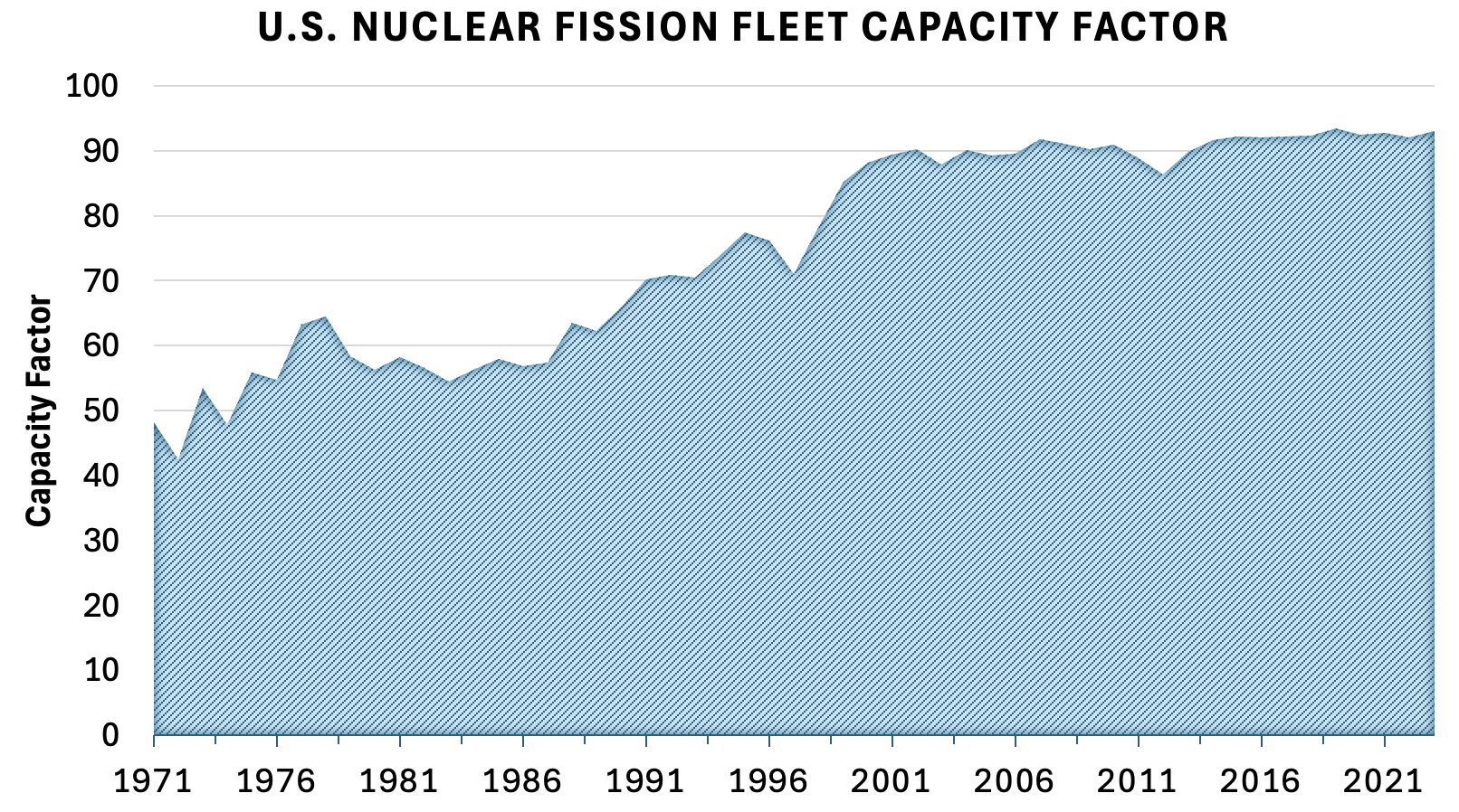
Figure 1: Historical U.S. nuclear capacity factor, motivating the FOAK utilization floor for Yinsen.
By focusing on a conservative blanket-area-normalized power density of Pf/Sb=0.7 MW/m2—anchored by the cumulative damage limit of the solid blanket and vessel—the design fundamentally lowers neutron-induced DPA (displacements-per-atom) exposure (Ldpa=35, F=5 DPA/(MW⋅yr/m2)), achieving a vessel lifetime matching the full plant duration at a utilization floor U=0.4. This materially-relaxed approach eschews the grid-centric drive for exceptionally high recirculating power and stringently optimized levelized cost of electricity (LCOE), prioritizing availability, ease of maintenance, and deployment viability in environments where fuel autonomy, dispatchability, and compatibility with maritime or industrial regulations override commoditized energy pricing.
The resultant upper bound on attainable power density in such a structural-materials-limited regime is summarized in Figure 2.
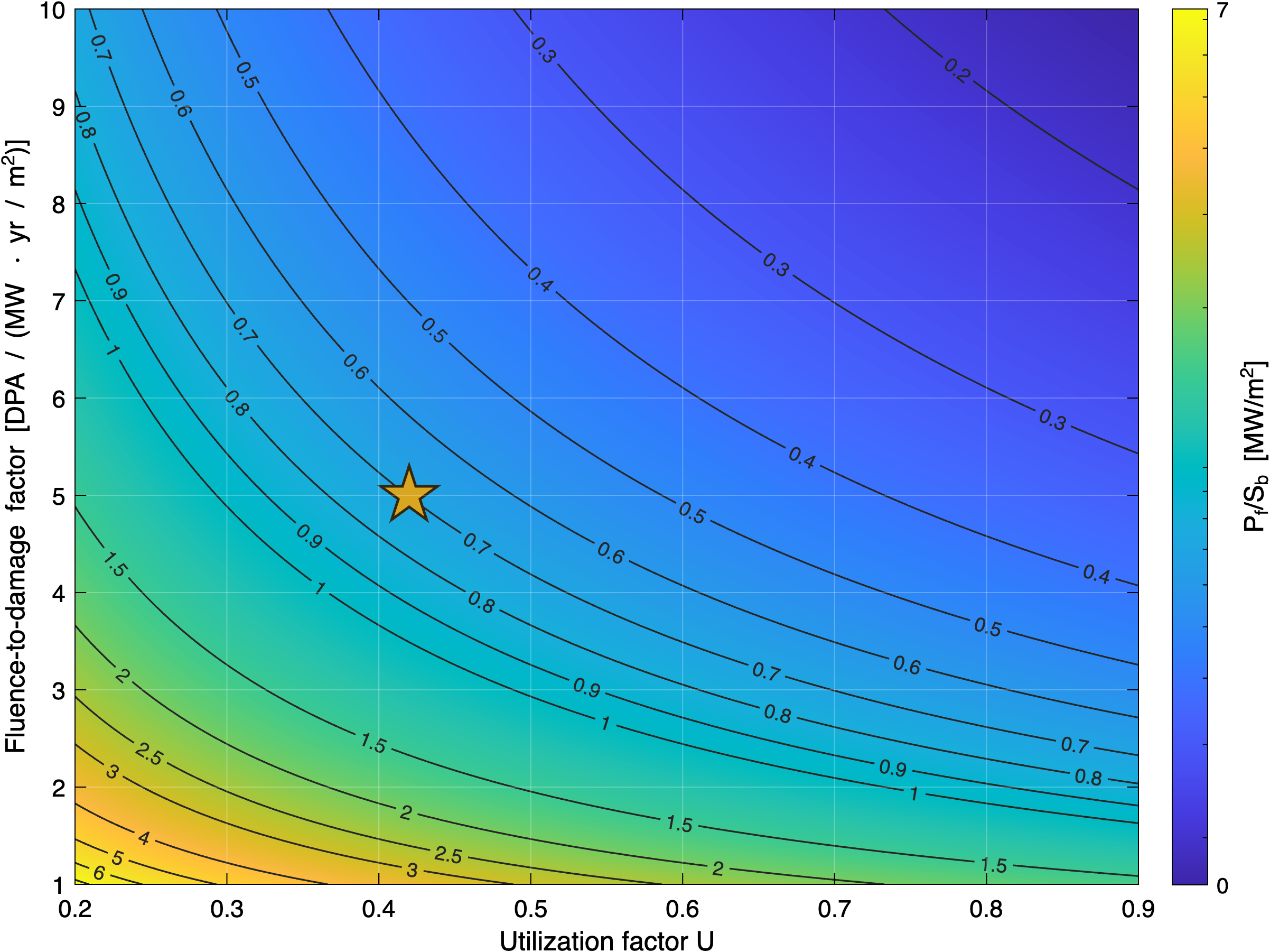
Figure 2: Damage-limited upper bound on blanket-area-normalized fusion power density versus utilization and fluence-to-damage conversion; Yinsen adopts 0.7 MW/m2 as a FOAK ceiling.
Tokamak Design Point and Parameterization
Given the structural-materials constraint, the minimum relevant net electric output for off-grid applications is defined as 25 MWe—matched to primary industrial and maritime demand thresholds. The corresponding net power balance, incorporating realistic recirculating and auxiliary loads (ICRH, cryo, tritium handling, FLiBe pumping), requires a baseline fusion power of 130 MW to achieve the net export after internal consumption (Q>10; ICRH efficiency ηwall→plasma=0.6).
Mapping Pf/Sb and Ldpa=350 onto machine size with conservative profile and geometric scaling yields a major radius Ldpa=351 m, minor radius Ldpa=352 m, and aspect ratio Ldpa=353 with high elongation Ldpa=354. The blanket-facing area Ldpa=355 tightly couples core geometry to the damage-limited power density. The required on-axis toroidal field is Ldpa=356, staying within REBCO HTS magnet-system capabilities and allowing a Ldpa=357 plasma current with Ldpa=358, well above typical operational stability thresholds.
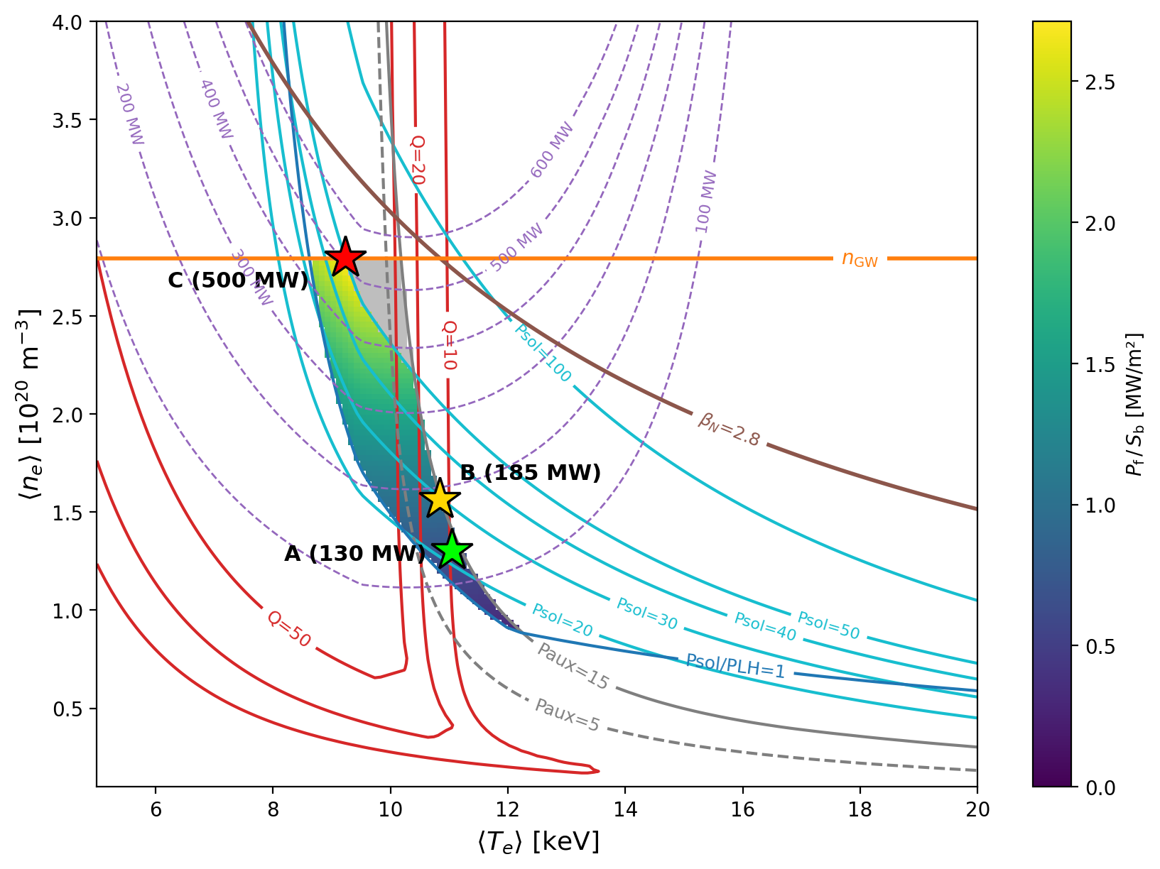
Figure 3: POPCON-style operating-space map for Yinsen, demonstrating inherently higher accessible power density, yet baseline operation constrained primarily by structural damage, not plasma-limit regimes.
Plasma Physics Analysis
The target steady-state scenario features centrally peaked but broad pressure and toroidal current density profiles, supporting a non-pathological monotonic Ldpa=359-profile while securing a substantial safety margin for both F=5 DPA/(MW⋅yr/m2)0-limit and neoclassical tearing stability. Bootstrap current fraction is modest (F=5 DPA/(MW⋅yr/m2)125%), reinforcing the maintenance of a robust inductive drive scenario consistent with marine-transient operational tolerances.
The power-balance analysis (Figs. 4, 5) demonstrates that alpha heating dominates the bulk core, while ICRH is well confined with high first-pass absorption (F=5 DPA/(MW⋅yr/m2)2, see below). The solenoid and poloidal field configuration, verified via time-dependent TokaMaker analysis, confirms feasibility of long-pulse flattop discharge (900 s), with robust vertical stability margins exceeding F=5 DPA/(MW⋅yr/m2)3 cm initial displacement—supported by thick passive conductors and PF coils.
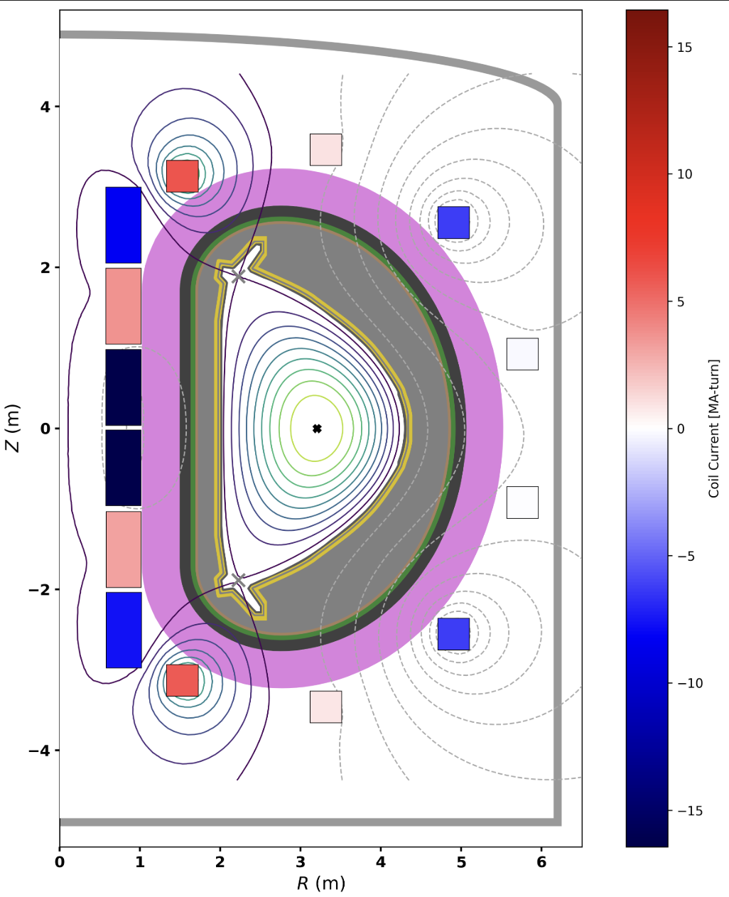
Figure 4: Nominal build and flattop equilibrium. All coils, shield, and cryostat are internal to the integrated assembly.
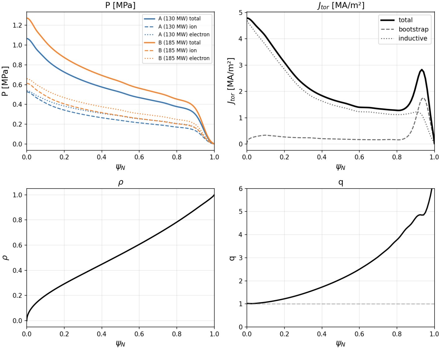
Figure 5: Initial equilibrium summary with pressure, current, radius, and safety-factor profiles, highlighting compatibility of Case A and B pressure states with relaxed F=5 DPA/(MW⋅yr/m2)4 and non-inductive current profiles.
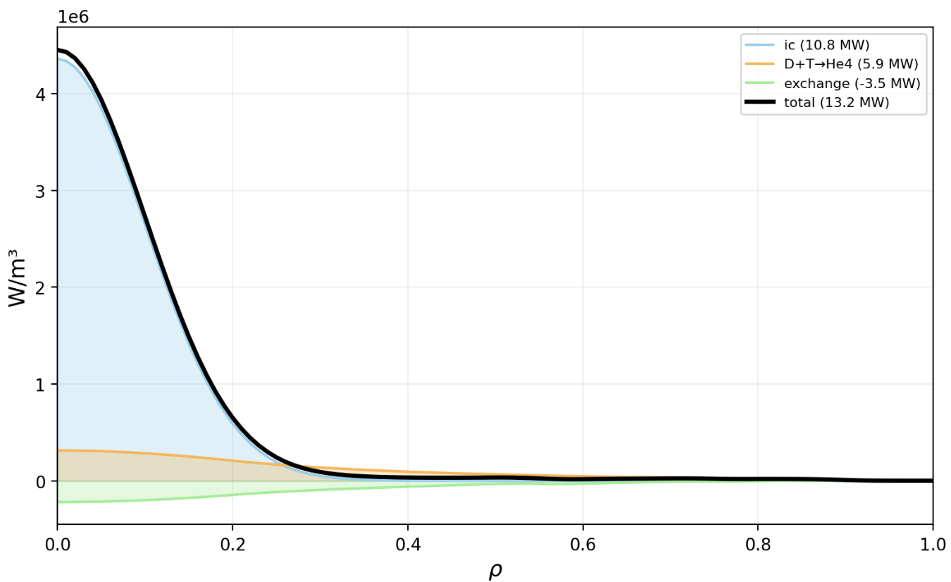
Figure 6: Ion-channel power sources/sinks: dominant alpha and ICRH heating, ohmic and radiative losses in baseline FUSE design.
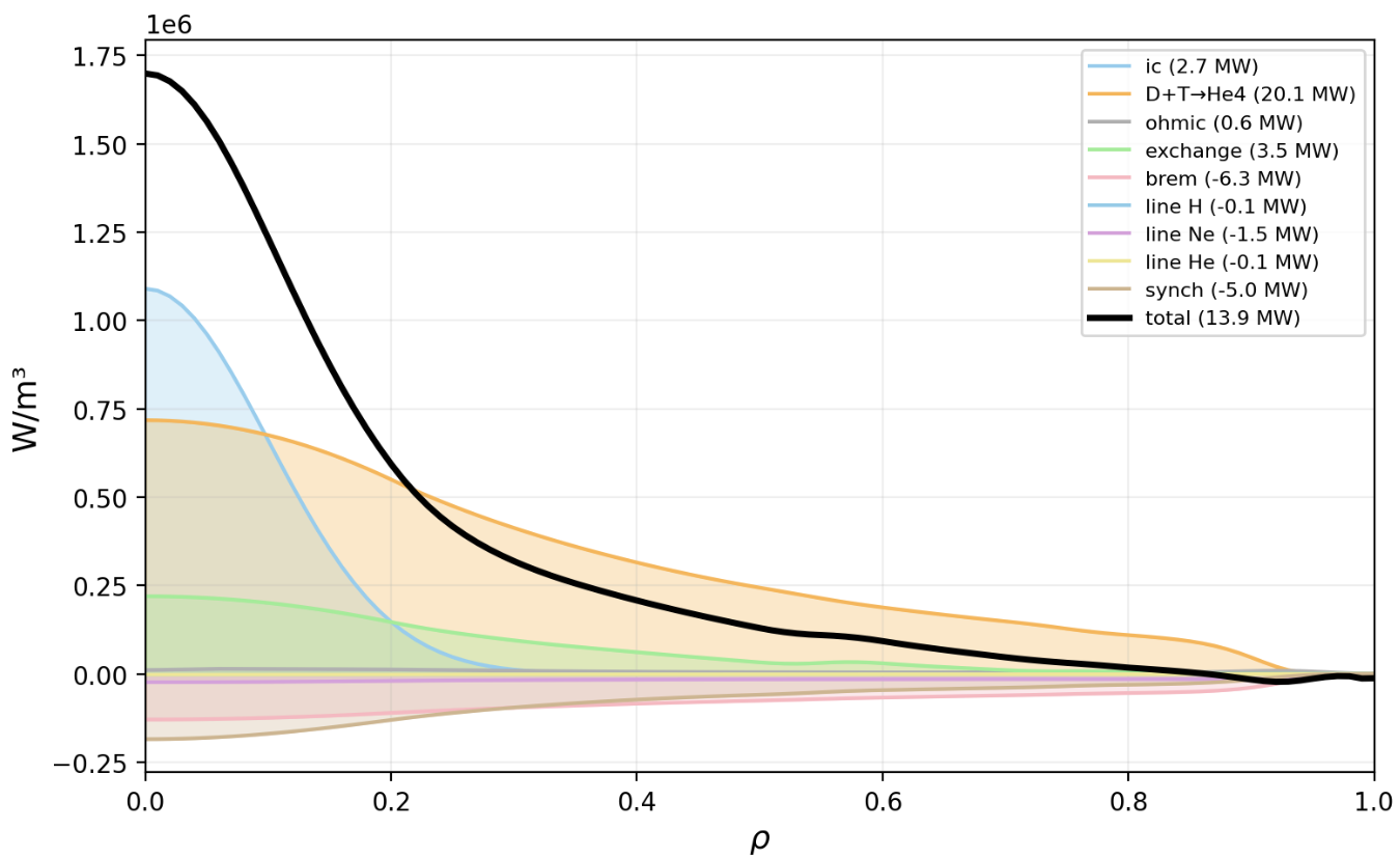
Figure 7: Electron-channel power sources/sinks: radial contributions and the net total source, validating energetic self-consistency with F=5 DPA/(MW⋅yr/m2)5130 MW fusion power.
Core Transport and Edge Pedestal
Transport predictions are validated using both a neural-network surrogate (TGLFNN+FUSE) and high-fidelity ASTRA+TGLF solvers. Agreement is typically within profile uncertainties, with pedestal-top conditions (density and temperature) exerting a dominant control over global fusion output (Figs. 12, 13). The reactor core operates in a stiff-transport regime: fusion performance is not strongly sensitive to moderate variations in ICRH efficiency or core F=5 DPA/(MW⋅yr/m2)6. Reliable real-time actuators for output control are thus identified as edge fueling and D-T ratio tuning rather than core heating (Fig. 14).
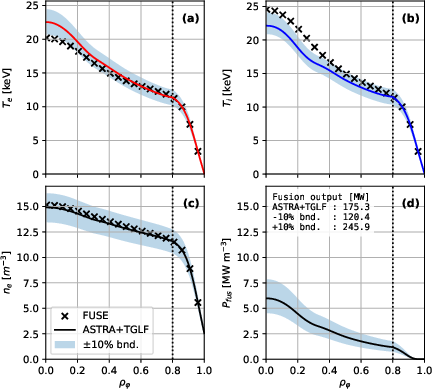
Figure 8: Core transport modeling for low power scenario—FUSE benchmarks are validated against ASTRA+TGLF predictions with boundary uncertainties.
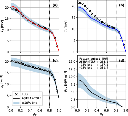
Figure 9: High power scenario shows similar profile agreement; output variation is bounded within F=5 DPA/(MW⋅yr/m2)7 pedestal-top uncertainty.
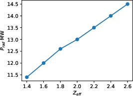
Figure 10: Radiated power scaling with F=5 DPA/(MW⋅yr/m2)8, demonstrating limited impact of impurity fraction on core performance.
Pedestal-top pressure and separatrix operational space are mapped (Fig. 15), with the operational point intentionally tuned for access to quasi-continuous exhaust (QCE) regimes, supporting radiative detachment—critical for power handling, especially in the divertor.
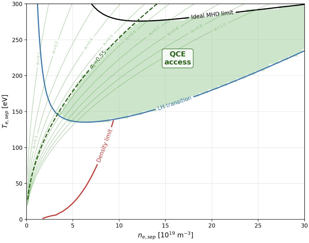
Figure 11: Separatrix operating-space for Yinsen; high F=5 DPA/(MW⋅yr/m2)9, moderate U=0.40 access QCE edge regime, avoiding Type-I ELMs configuration.
ICRH RF Heating and Minority Scheme
Yinsen's heating is entirely via ICRH leveraging a minority-hydrogen/second-harmonic-deuterium resonance at the magnetic axis (U=0.41 MHz), selected for both absorption efficacy and RF system packaging viability. First-pass absorption robustness to minority fraction and core temperature is evidenced in Figs. 16, 17; broad electron Landau damping is expected (non-negligible off-axis absorption at fusion-relevant temperatures), but with carefully controlled launch configuration, core heating is maximized and impurities are minimally generated.
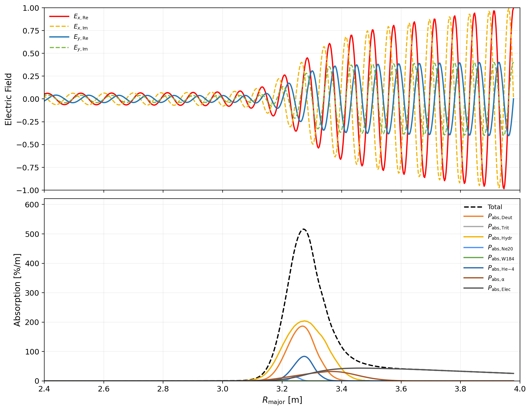
Figure 12: CARDS-modeled ICRH wave fields and absorption for Yinsen; first-pass absorption U=0.42 in reference scenario.
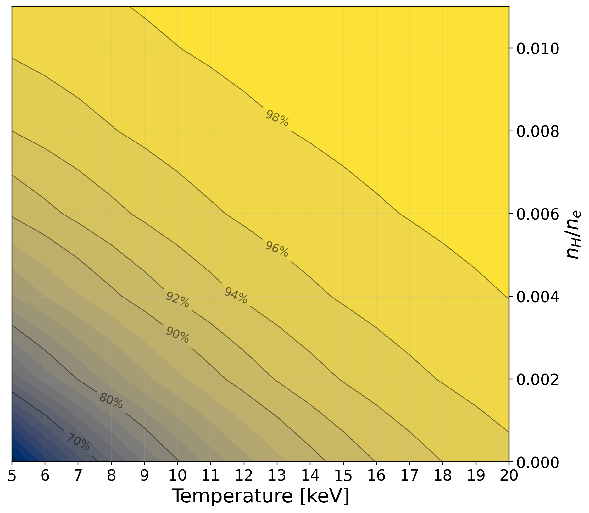
Figure 13: First-pass absorption is sustained over U=0.43 across reactor-relevant U=0.44. Startup scenarios may deploy enhanced minority seeding to guarantee startup robustness.
Power Exhaust and Divertor Engineering
SOL width estimation (U=0.45 mm) points to extreme upstream power concentration, though Yinsen's overall U=0.46 remains low enough for effective radiative detachment using seeded neon or other medium-U=0.47 impurities. UEDGE modeling produces robust detachment with outer target plate heat loads suppressed to U=0.48U=0.49 MW/m0.7 MW/m20 (Figs. 20–23), far below the threshold for tungsten monoblock failure and with comfortable operational margin (Figs. 24–25). The sensitivity of target plate surface temperature to coolant channel size and flow velocity is mapped, reinforcing that even conservative smooth-tube models ensure sub-recrystallization maximums (0.7 MW/m21C), with explicit further margin available via swirl-tube technology.
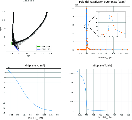
Figure 14: UEDGE base case with 0.7 MW/m22 m0.7 MW/m23: geometry and normal heat flux profile on the target, confirming 0.5 mm SOL width.
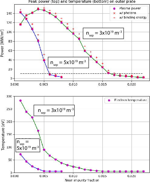
Figure 15: Peak power flux and plate temperature vs. 0.7 MW/m24 and Ne impurity fraction. Detachment and survivable temperature achieved with Ne 0.7 MW/m25 at reference conditions.
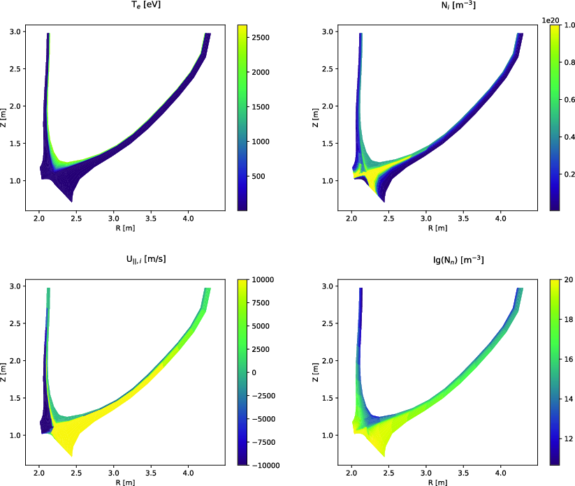
Figure 16: Full profile of a fully-detached baseline case, 0.7 MW/m26 MW, Ne 0.7 MW/m27; peak heat flux 0.7 MW/m281 MW/m0.7 MW/m29 on tungsten.
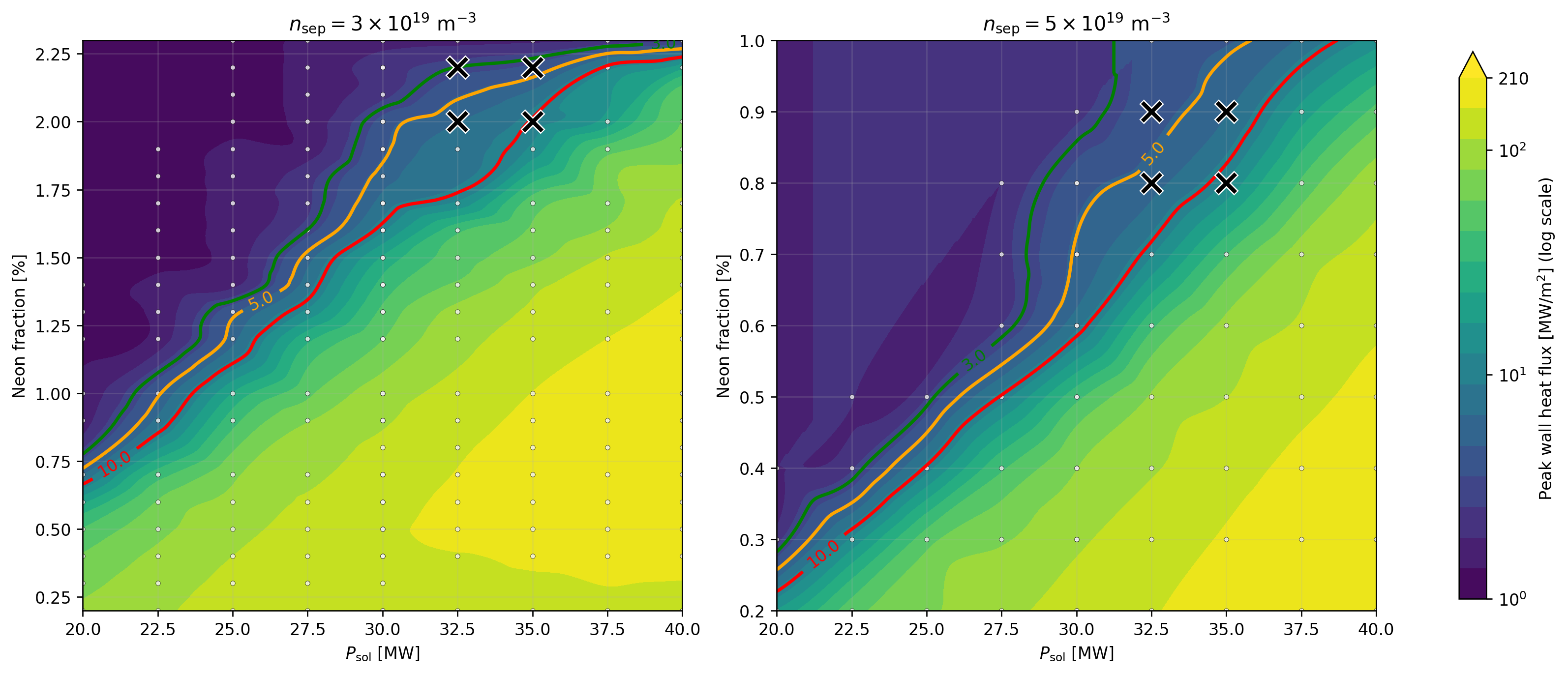
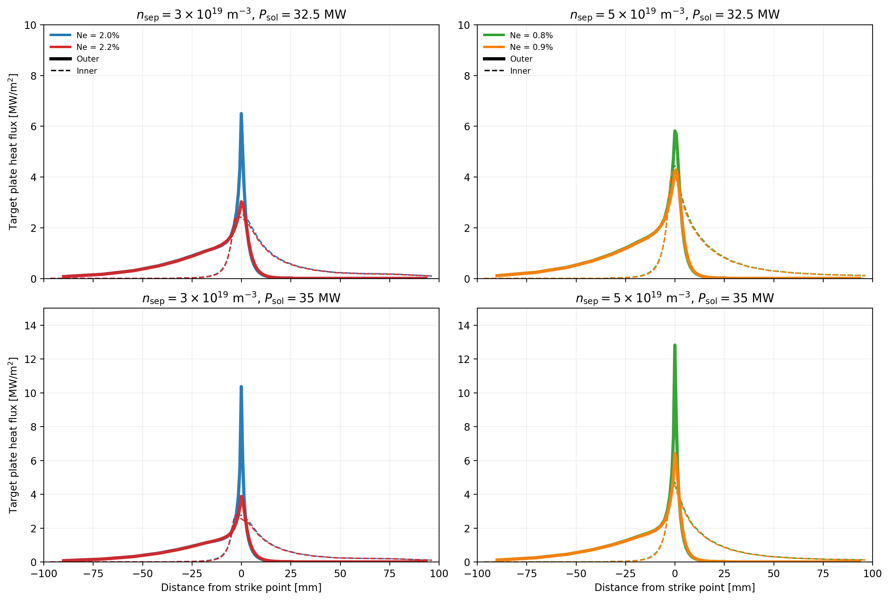
Figure 17: Detachment boundary as a function of 25 MWe0 and Ne impurity, quantifying operational space for safe divertor performance.
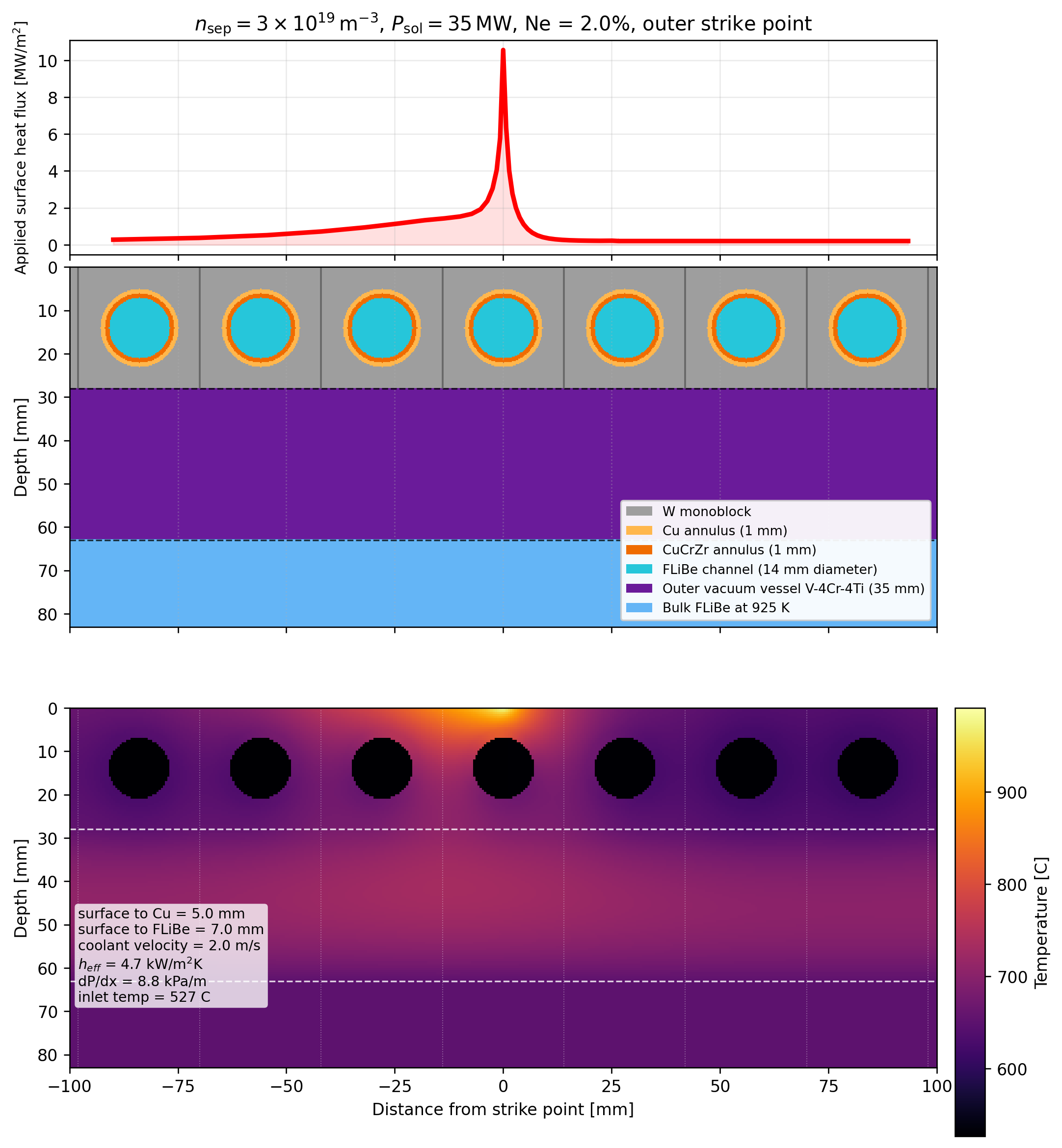
Figure 18: Monoblock target plate design: simulated surface heat-flux profile and corresponding 2D temperature field at FLiBe 25 MWe1 m/s.
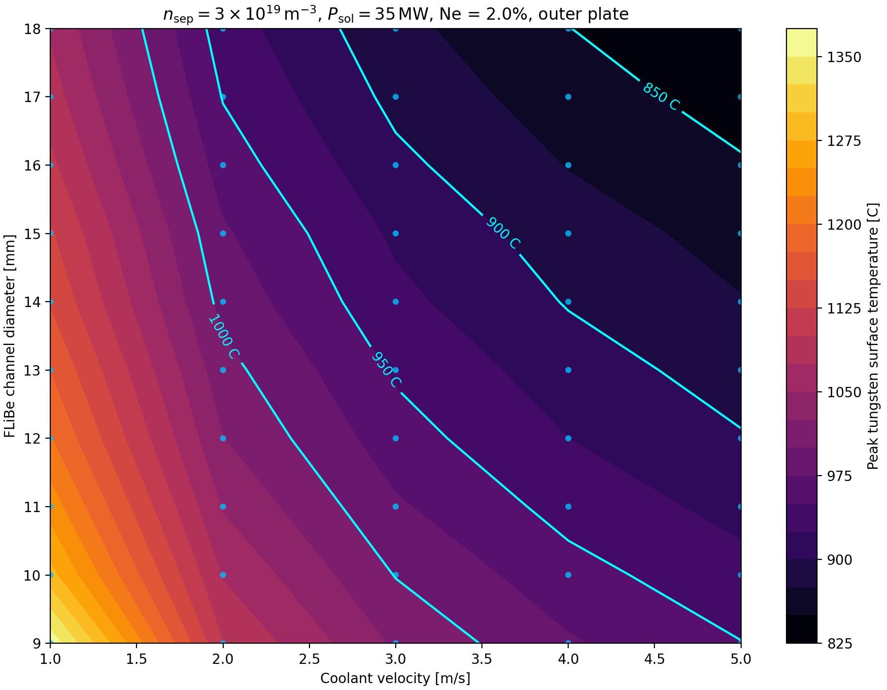
Figure 19: Peak tungsten surface temperature in detached regime as a function of FLiBe channel geometry and speed, demonstrating all values remain below critical.
Magnet Engineering and Structural Survivability
All confinement and shaping magnets utilize modular REBCO-based HTS technology (SHIELD cable architecture), facilitating fast ramping and maintenance, and providing manufacturing synergy with power-distribution applications. The TF coil system employs insulated double pancakes (25 MWe2 kA/coil, 25 MWe3 T on conductor), with robust outer inter-coil support and wedge-based self-loading to react centering forces. Structural FEA analysis shows maximum von Mises stresses at the inboard midplane (25 MWe4 MPa) remain well within allowable for SS316LN at 25 MWe5 K, with dominant load being passively shared among the outer shells and OIS attachments.
Neutronics, Shielding, Tritium Breeding, and Activation
OpenMC simulations validate the blanket/shield stack-up, balancing breeding (TBR 25 MWe6), energy recovery, and activation. The design achieves 25 MWe7 DPA/year at 25 MWe8 MW, ensuring the 25 MWe9 DPA limit is reached after 20 years of operation—the intended design point. The HTS magnet system is shown to be non-limiting: fast-neutron flux at the conductor positions allows TF lifetimes exceeding sixteen full vacuum vessel durations.
The blanket leverages a V-4Cr-4Ti vessel for low neutron parasitic absorption, allowing relaxation on 130 MW0Li enrichment to 130 MW1 without a multiplier. Activation analyses reveal that the majority of in-vessel components fall below recycling thresholds within 130 MW2 years, a timescale far shorter than for aggressive high-power-density designs.
Pulsed Power Operation, Plant Modeling, and Energy Storage
Yinsen adopts long-pulse (900 s flattop) operation with inductive current drive, using a modular solid-state transformer and energy storage backbone (battery-capacitor hybrid, Figure~\ref{fig:storage_alpha_2d}). The plant’s pulsed-duty power flow and energy storage requirements are optimized for lifetime cost and operational margin, with storage architectures allowing both routine pulsed energy buffering and extended ride-through for essential loads.
Balance of Plant and System Sizing
Primary heat transport uses single-phase FLiBe at 130 MW3 K, coupled to a supercritical CO130 MW4 Brayton cycle (130 MW547.5% cycle efficiency), supporting compact secondary conversion and high net plant efficiency (42.6–50.4% depending on size). Modularization of FLiBe loops, heat extraction, and conversion is consistent with both station and marine integration footprints (Fig.~\ref{fig:facility_layout_direct_capex}).
Capital Cost, Shipping Economics, and Deployment Prospects
A detailed bottom-up direct overnight-capital screen estimates FOAK cost at 130 MW6 MUSD, dominated by REBCO, W130 MW7B130 MW8 shield, and FLiBe inventories. Auxiliary systems (cryoplant, tritium plant, power conversion) are nontrivial but scalable. Shipping economic analysis, leveraging break-even LCOT, indicates that post-learning-curve NOAK units (130 MW9 MUSD target) begin to approach competitiveness with methanol and VLSFO propulsion in high-speed, high-carbon price shipping service (Fig.~\ref{fig:shipping_breakeven_cases}).
Implications and Future Prospects
Numerical results: At Q>100 MW, net electric output is Q>101 MWe, Q>102, Q>103, energy confinement Q>104 s, Q>105, and Q>106 keV. Detached divertor operation is sustained at Q>107 MW/mQ>108. Total tritium inventory is Q>109 g; doubling time is ηwall→plasma=0.60 days. Activation and mechanical loading confirm lifetime structural limits are not exceeded, while magnet and auxiliary systems are lifetime components under the adopted envelope.
Contrasts/claims: The paper claims, in contrast to commonly cited compact HTS grid-competitive tokamak concepts, that a pragmatic reduction in power density enables a credible first-of-a-kind reactor with manageable replacement, shielding, activation, divertor, and tritium-inventory constraints, at little penalty to achievable net power or reactor reliability for off-grid use.
Further gains in reactor competitiveness for maritime or islanded applications are tethered less to plasma performance and more to supply-chain learning in HTS tape, high-mass neutron shields, and plant modularization. The predicted material and operational envelope of Yinsen supports the thesis that the first valuable fusion systems will be buildable, modular, and serviceable, targeting niche but high-value domains rather than bulk grid integration.
Conclusion
Yinsen demonstrates that low power density HTS tokamak reactors, engineered for off-grid and maritime applications, can achieve practical net electric output with manageably low neutron damage, activation, and power-handling burden, without compromising plasma physics or operational reliability. By anchoring the reactor to a materials-limited envelope, the study identifies a commercialization pathway for fusion energy that; while not optimized for grid cost minima, is highly pertinent where availability, autonomy, and operational flexibility are paramount. The work’s results indicate that the most significant future advances will arise from developments in materials durability, robust pulsed-operation system design, tritium processing, and maritime-optimized packaging, substantially lowering deployment barriers for early-market fusion reactors and broadening the landscape of credible fusion-energy applications.