- The paper introduces a novel single-stage optimization method that simultaneously determines plasma equilibrium and coil currents.
- The study quantifies tradeoffs among rotational transform, QS error, plasma volume, and coil force under strict HTS limits.
- The design offers reconfigurable modes for QA stellarators and tokamak regimes, enhancing diagnostic access and shaping control.
Feasibility Analysis of a Flexible Hybrid Tokamak-Stellarator Utilizing an Axisymmetric Dipole Coil Array
Introduction
This work systematically addresses the design space and feasibility of a university-scale, hybrid tokamak-stellarator device constructed around an axisymmetric, planar high-temperature superconducting (HTS) dipole coil array (2606.13326). The chosen approach provides a limited set of geometric degrees of freedom for the shaping coils, with the underlying geometry inspired by the HBT-EP experiment. The chief innovation is the employment of simultaneous (single-stage) optimization of coil currents and plasma equilibrium, leveraging two-stage equilibrium/coil initializations to converge to solutions consistent with demanding engineering and physics constraints. The device's parameter space is interrogated with respect to achievable rotational transform, quasi-symmetry (QS) error, plasma volume, coil current, and associated engineering ranks, all while delineating the respective physical and engineering tradeoffs dictated by the compact and constrained coil geometry.
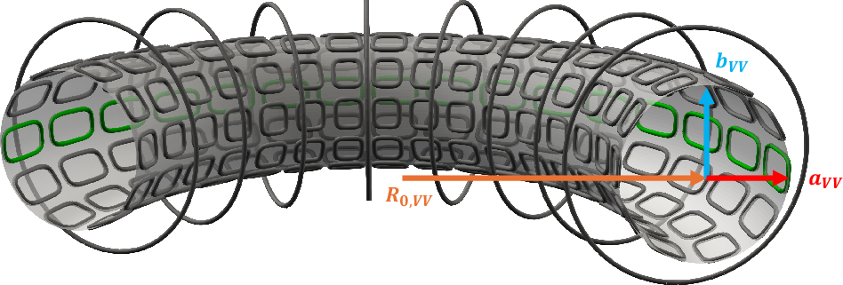
Figure 1: Illustration of the axisymmetric array of dipole coils (dark grey) and vacuum vessel (light grey) spanning 180∘ in toroidal angle; outboard coils that may be removed to increase diagnostic access are indicated in green.
Optimization Framework and Device Design
Motivation and Constraints
In a standard stellarator, intricate non-planar coils are optimized for 3D shaping but present significant manufacturing and cost obstacles. Hybrid approaches—wherein only a fraction of the rotational transform is externally supplied—mitigate both engineering complexity and profile control issues, provided that external fields exhibit high QS or omnigenity. The present axisymmetric dipole array maintains a fixed vessel geometry with only three continuous parameters, plus two discrete variables (poloidal/toroidal coil multiplicity), strictly bounding the accessible configuration space.
A principal engineering constraint is the HTS Lorentz force limit, capped well below $4$–8×10⁵ N/m for coil selection. An analytic self-force model provides primary screening, though net (integral) support forces and mechanical torques are acknowledged but not yet exhaustively resolved.
Multi-Stage Optimization Execution
The design pipeline couples conventional two-stage optimization (stage-I: Fourier-based equilibrium boundary optimization; stage-II: minimal-error coil current solution at fixed geometry) with hot-started, fully-coupled single-stage optimization for simultaneous plasma and coil solutions. The degeneracy in coil current solutions is handled by employing minimal regularization during initializations and explicit norm constraints in the single-stage objective, thereby tightly bounding the emergent coil force profiles.
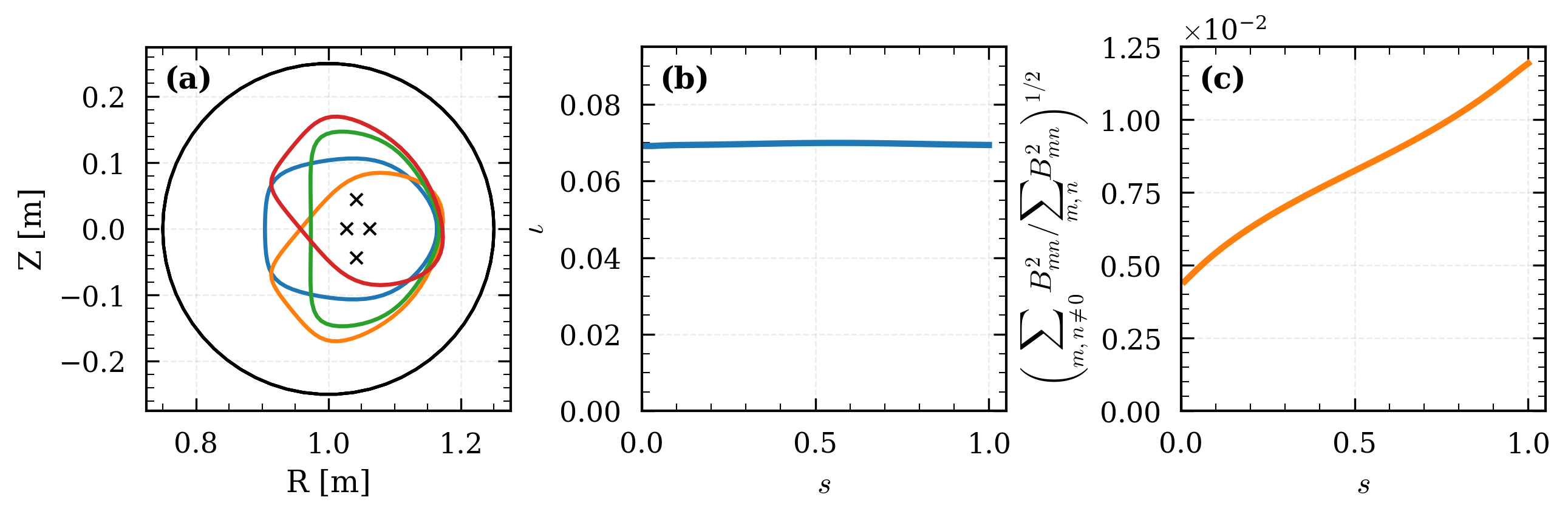
Figure 2: (a) Optimized equilibrium cross-sections at several toroidal positions with magnetic axis (black X) and vessel limit (solid line); (b) resultant ι-profile; (c) square root of Boozer quasi-axisymmetry-breaking strength versus normalized toroidal flux.
Pareto Front Analysis
Vessel baselines and coil multiplicities are scanned to map the achievable tradeoff between surface field error and maximum coil current across the geometric parameter space. Notably, as poloidal coil number increases, solutions admit lower field error at the cost of higher coil current, but only Nθ≥10 can meet the <0.5% field error criterion suitable for successful single-stage optimization (see discussion corresponding to Figure 3 in original text).
Coupled Optimization Tradeoffs
Single-stage vacuum optimizations reveal a tightly bounded axisymmetric envelope—the configuration is limited on the inner/outer edges by minimum current and field error constraints, respectively. Scans over rotational transform target (ιT), norm-constrained current ITp=20, and plasma volume VT, all at fixed vessel geometry, show that maximization of one parameter is necessarily achieved at the expense of others, and that the minimum QS error saturates at small ι, independent of further current scaling.
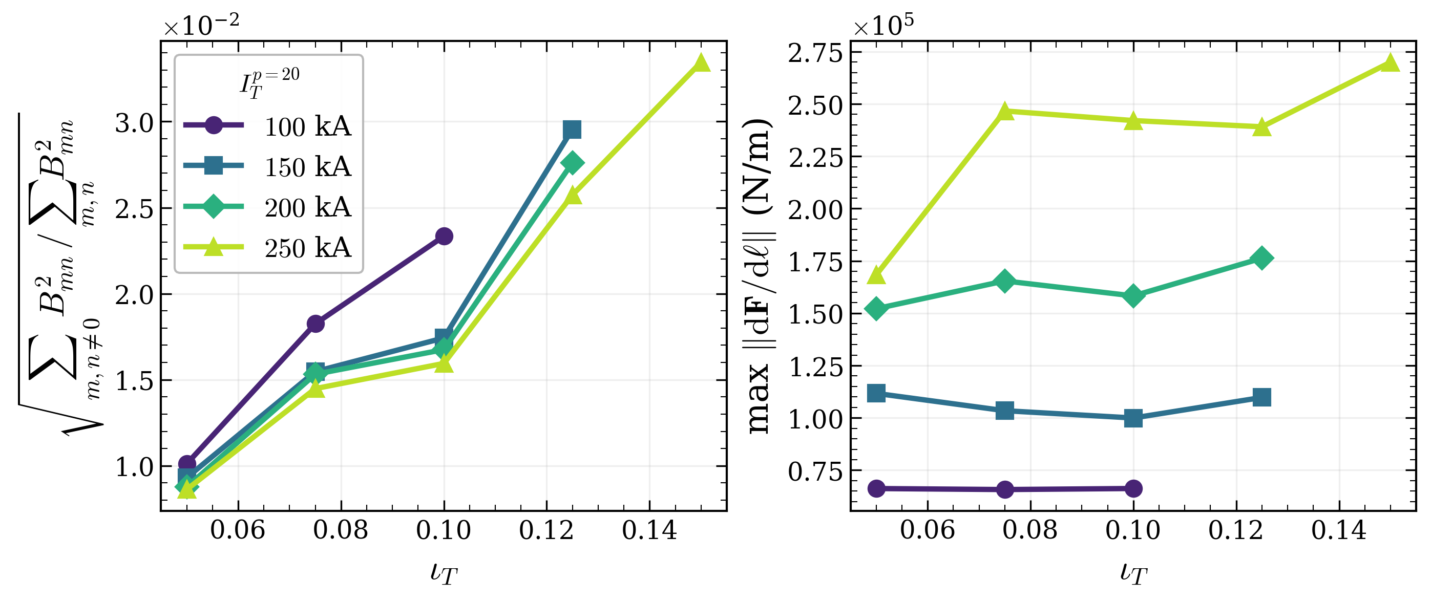
Figure 3: (Left) Minimum achievable Boozer QS error as function of $4$0 for several current thresholds; (Right) Maximum per-unit-length coil force throughout the scan.
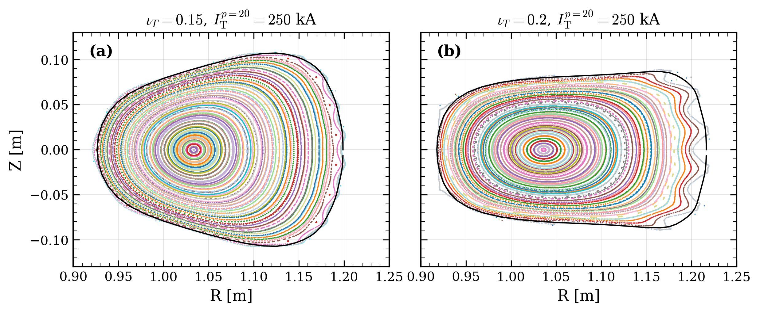
Figure 4: Representative Poincaré plots for (a) an acceptable $4$1 case (nested surfaces), and (b) a rejected $4$2 case (chaotic island formation).
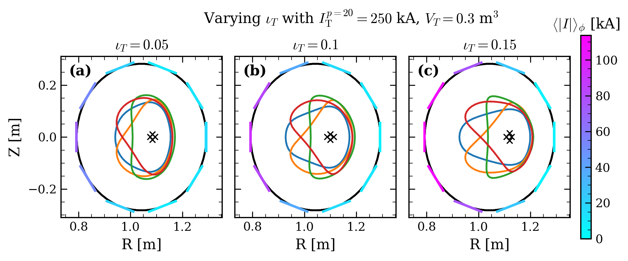
Figure 5: Cross-sections and axis loci for increasing $4$3 with fixed current norm, indicating increased non-axisymmetric shaping with larger $4$4; coloring denotes toroidally integrated coil current.
Geometrical Interpretation
Volume scans demonstrate that, to first order, the axisymmetric envelope is invariant; attempts to scale up the plasma volume at fixed transform target are ultimately adjudicated by unacceptable QS error increase and/or force constraint violation. The geometric shaping is primarily in the inboard region, with optimization-driven current localization mirroring the poloidal shaping locus.
Engineering Flexibility: Sparsity, Finite-$4$5 Extensions, and Tokamak Regimes
Sparsity and Diagnostic Accessibility
By exploiting the observed negligible outboard coil contribution in many optimized cases, the array can tolerate removal of outboard coils with only moderate degradation (10–20%) in QS error and sustaining similar transform levels—thereby substantially enhancing port access for diagnostics and auxiliary systems.
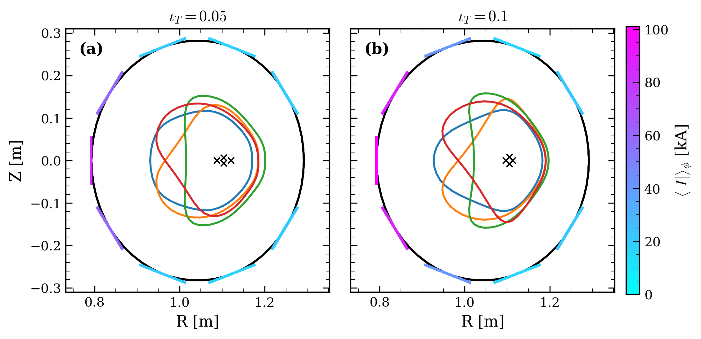
Figure 6: Magnetic surface cross-sections for sparse coil case with outboard coils removed; good quality QS with retained transform is maintained.
Finite-β Operation
Analysis with realistic HBT-EP experimental pressure and toroidal current profiles demonstrates that plasma β effects (modeled via VMEC) do not significantly worsen the QS error—indeed, at some radii QS can improve slightly—though maximum coil currents increase by approximately 30%. Re-optimization can be restricted to coil currents only, as surface shape variations are minor.
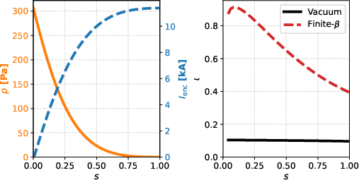
Figure 9: (Left) Imposed pressure/toroidal current profiles; (Right) their impact on $4$6 profile for vacuum versus finite-β equilibrium.
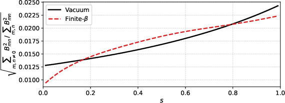
Figure 11: QS error versus flux-surface label $4$7 for vacuum (black) and finite-β (red dashed) equilibria—demonstrating minimal QS penalty of increased β.
Tokamak-Mode Utility
The axisymmetric dipole array is reconfigurable for pure tokamak regimes as both a ripple correction system (allowing $4$8 reduction in required TF coil number) and as an effective shaping/PF coil array to achieve strong shaping (e.g., $4$9, 8×10⁵ 0) in both positive and negative triangularity, within modest current budgets.
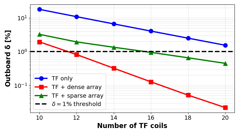
Figure 7: Ripple parameter 8×10⁵ 1 on the outboard midplane versus TF coil number for TF-only and TF-plus-dipole cases. Access to strong shaping at reduced TF coil count shown.
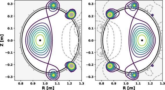
Figure 8: Double-null diverted tokamak equilibrium cross-sections for both negative (left) and positive (right) triangularity, obtained via reconfigured dipole currents; high elongation and accessible shaping demonstrated.
Parametric analytic construction of axis torsion and rotating ellipse deformations within a fixed axisymmetric envelope establishes that increased rotational transform necessarily demands reduction in plasma volume, as anticipated from near-axis theory.
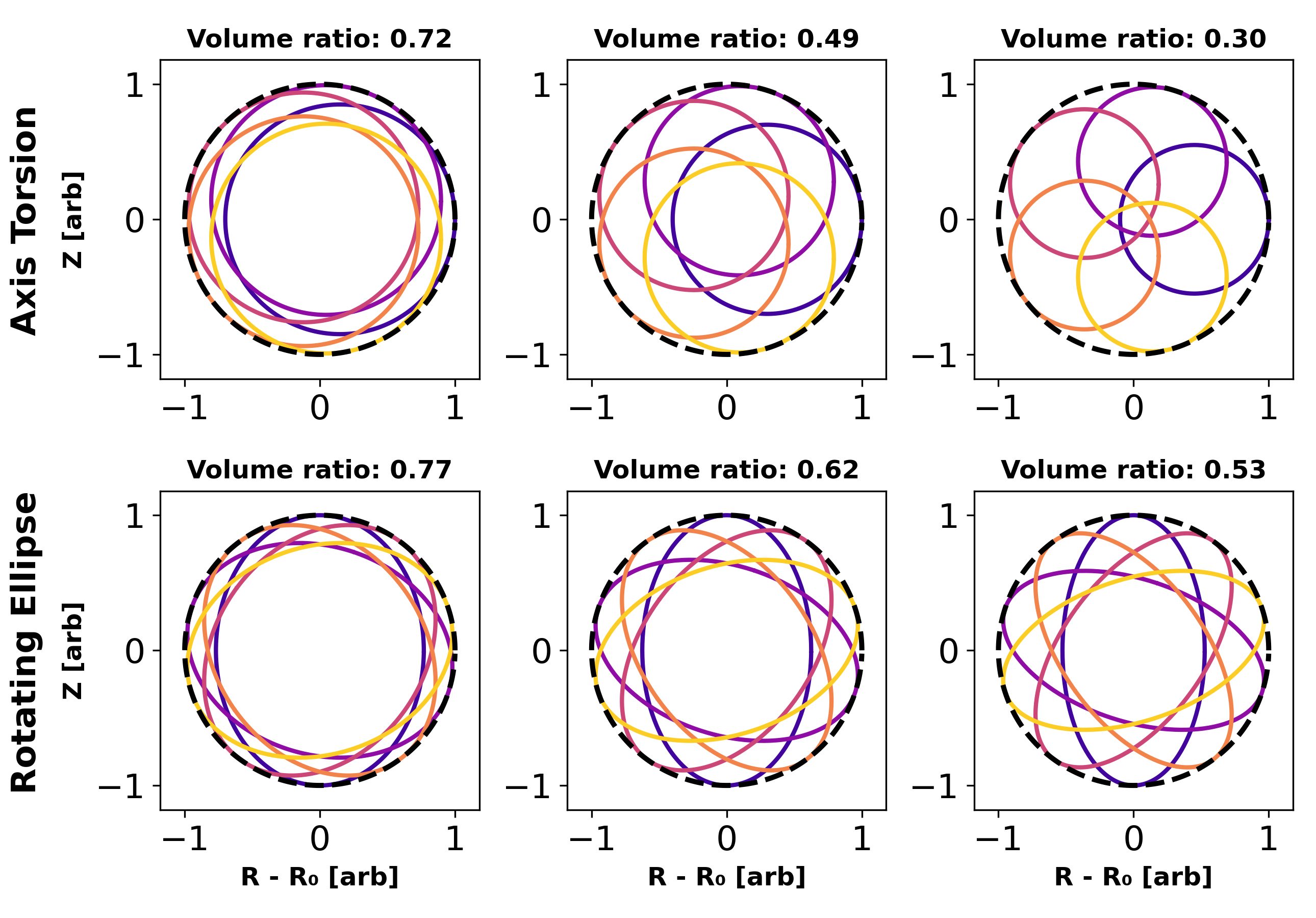
Figure 10: Analytic illustration of axis torsion (top row) and ellipticity modulation (bottom row) parameterized by amplitude—the tortuous or elliptical shaping incrementally reduces the enclosed plasma volume.
Implications and Future Directions
The established device concept demonstrates a versatile, reconfigurable experimental platform for studies spanning QA stellarators (8×10⁵ 2 up to 8×10⁵ 3), reactor-relevant hybrid equilibria with strong current drive, and access to advanced tokamak shaping and reduced TF coil scenarios. All configurations lie below critical HTS force density thresholds, leaving significant engineering headroom for future extension to more extreme equilibrium families (quasi-helical, quasi-isodynamic, or reduced-aspect-ratio branches). Open directions include geometric parameter expansion (e.g., ellipticity sweeping), integrated coil-and-support finite-element structural analysis, and inclusion of finite-build effects.
Robust optimization routines developed here, notably the single-stage approach tailored to limited-DOF coil arrays, should generalize to emerging pixelated coil and permanent magnet approaches across the fusion landscape. The ability to leverage hot-start heuristics, constraint-driven envelope control, and sparse array design will inform both advanced device construction and the physics program, particularly in experimental validation of MHD stability, ripple correction, and shaping-induced transport studies.
Conclusion
This study establishes that an axisymmetric dipole coil array can facilitate a highly flexible, university-scale hybrid tokamak-stellarator capable of supporting a wide range of QA, hybrid, and tokamak equilibria, all while remaining firmly within practical engineering constraints. The device can serve as a testbed for both fundamental questions in stellarator optimization and practical studies of advanced tokamak shaping and ripple correction. Future work should extend to alternate symmetry spaces, advanced field-periodicity regimes, and mechanical design integration to fully realize the potential of this architecture.
Reference: (2606.13326).

