- The paper introduces a dynamic simulation framework that uses explicit, probe-based contact models to accurately capture localized motion and transmission errors in precision reducers.
- It employs a modular API and numerical acceleration techniques for detailed sensitivity analyses of torsional stiffness, lost motion, and backlash under varying geometric errors.
- Results demonstrate that bearing clearance, eccentric radius, and phase angle errors critically impact performance, validating the toolkit's efficacy in high-precision reducer design.
Introduction and Motivation
The analysis and design of precision reducers, such as Planetary Gear Trains (PGT), Rotate Vector (RV) reducers, and harmonic/monocrank variants, are fundamental to the performance of high-end industrial and service robotics. The complex coupling of torsional stiffness, loss/windup motion, and transmission error (TE) mandates unified, high-fidelity modeling for system optimization, fault diagnosis, and precision control. Traditional Lumped Parameter Models (LPM), symbolic analytical frameworks, and commercial FEA face challenges in either computational tractability, poor adaptivity to arbitrary topology/geometries, or lack of physical interpretability. This paper introduces a dynamic toolkit that applies explicit, probe-based contact geometry and modular solver acceleration strategies, bridging the computational gap between high-DOF FEA and analytical rigidity. By leveraging explicit contact primitives, scriptable assembly, and numerical acceleration techniques, this toolkit enables highly resolved simulations for reducer topologies with hundreds of degrees of freedom (DOFs) and directly captures localized phenomena (e.g., needle-by-needle/individual tooth contact), essential for contemporary robotics applications.
The core of the toolkit is the replacement of rigid contact simplifications and black-box FEA with explicit, numerical contact models. Each physical contact—circle-circle for needle rollers, curve-circle for cycloid-pinwall, and curve-curve for involute pairs—is represented by a modular, unified API with analytic and fallback probe-based detection. This design ensures robust geometric fidelity even at singularities such as tooth tips and enables topological reconfiguration without symbolic derivation.
- The normal force for each contact is computed via a non-linear penalty law with smooth Hertzian exponent (fn=kmeshmax(0,−g)10/9), suppressing force discontinuities at the onset of contact. Friction is handled through regularized, velocity-dependent Coulomb models.
- For scalability, a four-stage detection pipeline is implemented: angular pre-screening, AABB filtering, warm-start active set search (leveraging temporal continuity for O(1) convergence), and block-skip fine search/probe fallback to avoid failure at degenerate geometries.
- The system supports direct, ANCF-based integration of flexible body dynamics, particularly relevant for the bearing-housing "hole-wall" ovalization phenomena under high radial load.
- Modular contact types (CC, CCv, CvCv) allow streamlined extension to arbitrary mechanical structures, including new gear families (e.g., harmonic drives, hypoid gears), by overriding only the prescreening and geometric representations.
Global System Assembly and Solver Architecture
The reducer is instantiated via scriptable composition: physical components (rigid or ANCF-flexible) and their coordinate markers are assembled, and contact pairs are inserted between markers as objects. The global dynamic equations incorporate all resolved contacts and drive constraints, integrating with a Generalized-α solver for controlled numerical dissipation and robustness to contact-induced stiffness. Discontinuous events (contact open/close) are managed by post-Newton-callbacks and adaptive timestep control, with Jacobian re-factorization only on changes in contact active set to optimize performance.
Numerical Experiments: Sensitivity and Hysteresis
The toolkit performs batch simulations under controlled, physically realistic geometric error perturbations reflecting IT3–IT6 manufacturing tolerances for the RV-320E reducer class. The principal quantities of interest—torsional stiffness KT, lost motion LM, and backlash BL—are extracted from hysteresis loops, whose shape and envelope are processed via offset correction and branch separation.
Key Result: The simulations are used to isolate the impact of eccentric radius error, eccentricity, phase angle error, and bearing radial clearance on the hysteresis metrics.
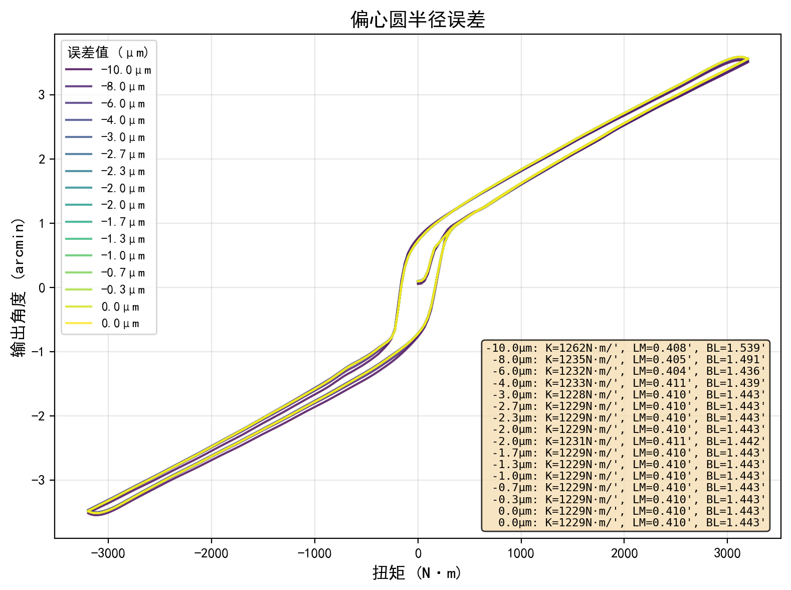
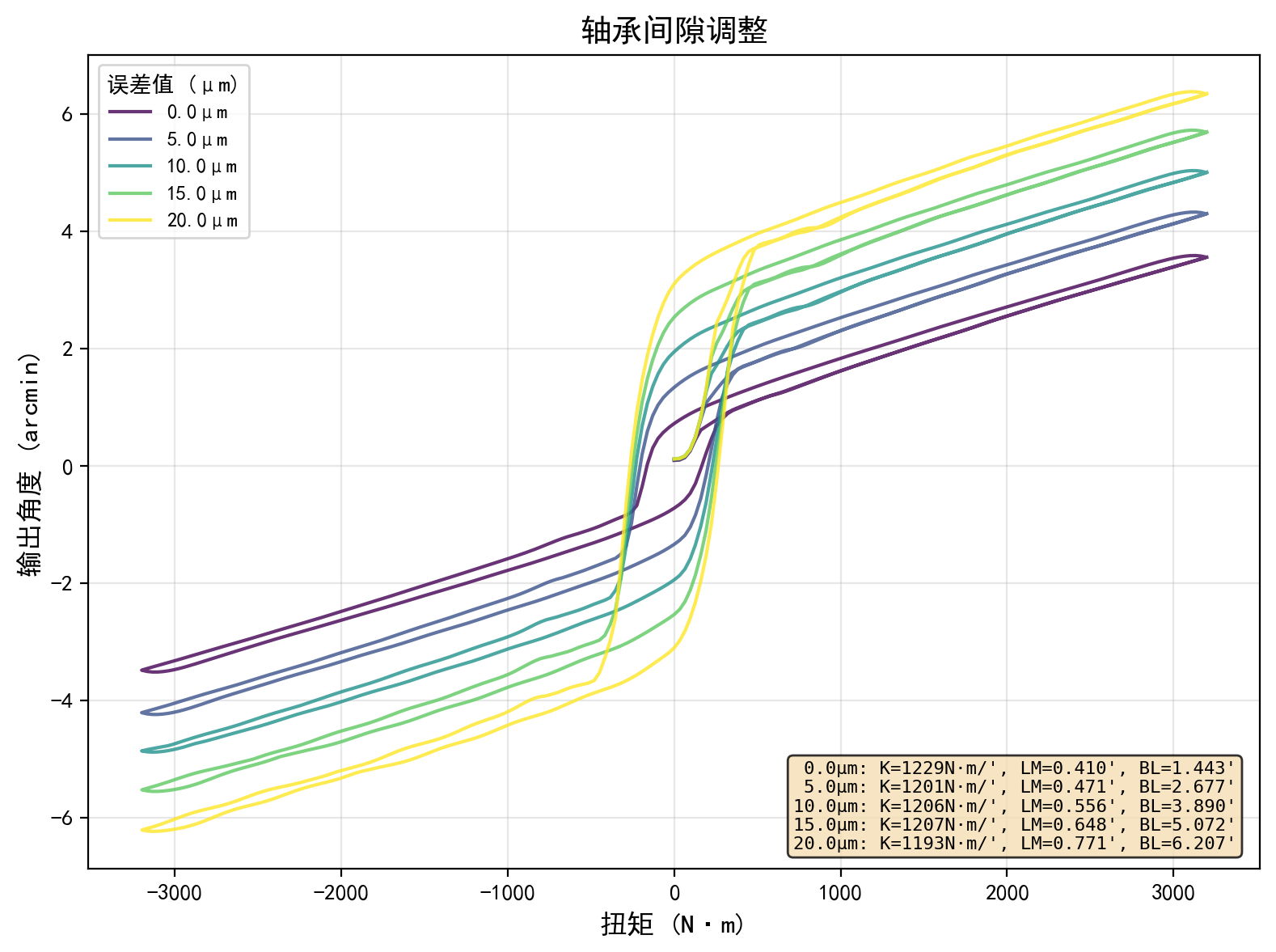
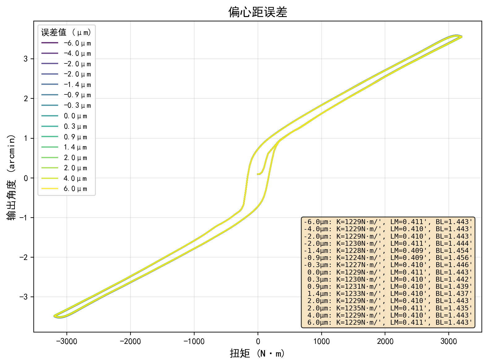
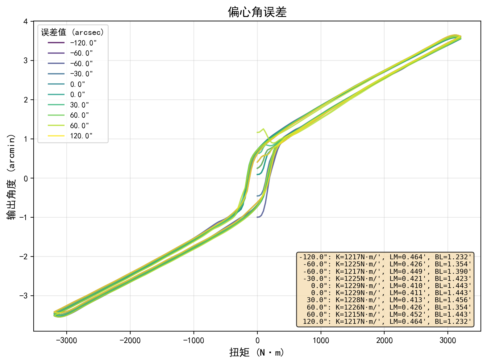
Figure 2: Hysteresis curves under varying geometric error conditions. Subplot (b) confirms that bearing clearance is the dominant driver of lost motion and backlash.
- Bearing clearance (δc) is identified as the dominant parameter influencing LM and BL. Increasing δc from 0 to O(1)0m produces an 88% rise in O(1)1 and a 330% increase in O(1)2, with a torsional stiffness decrease of only 2.9%. This finding quantifies the paramount importance of fit tolerance for high-precision reducers.
- Eccentric radius error mainly reduces O(1)3; a O(1)4m decrement yields a 2.6% stiffness decrease but negligible O(1)5/O(1)6 change.
- Phase angle error impacts O(1)7 and O(1)8 symmetrically (a O(1)9 shift results in a 13% α0 increase, 14.6% α1 reduction), highlighting the necessity for stringent phase synchronization, particularly in multi-crank designs.
- Eccentricity error has minimal effect (α2 on all metrics), suggesting tolerance requirements on this dimension can be relaxed for cost optimization.
Transmission Error and Local Error Effects
The explicit geometric modeling supports detailed assessment of instantaneous TE as a function of crank angle and under various error sources.
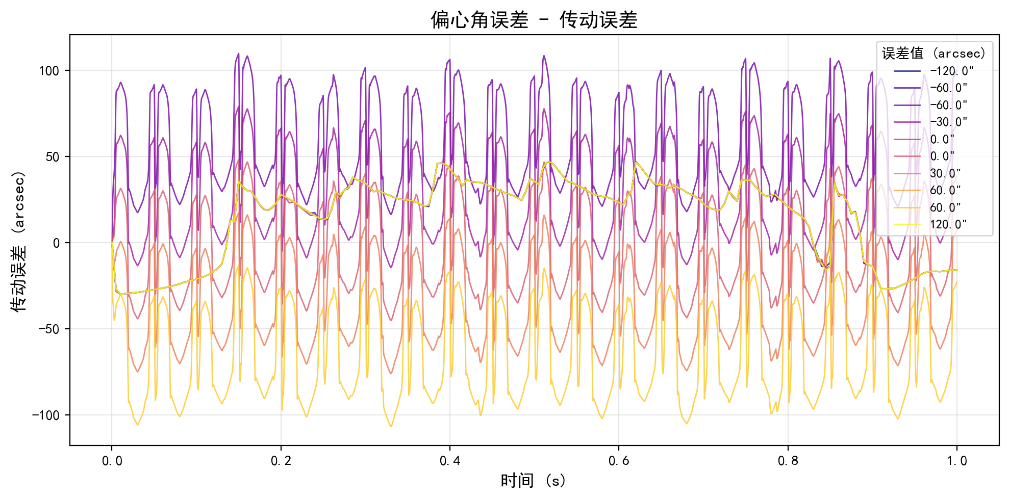
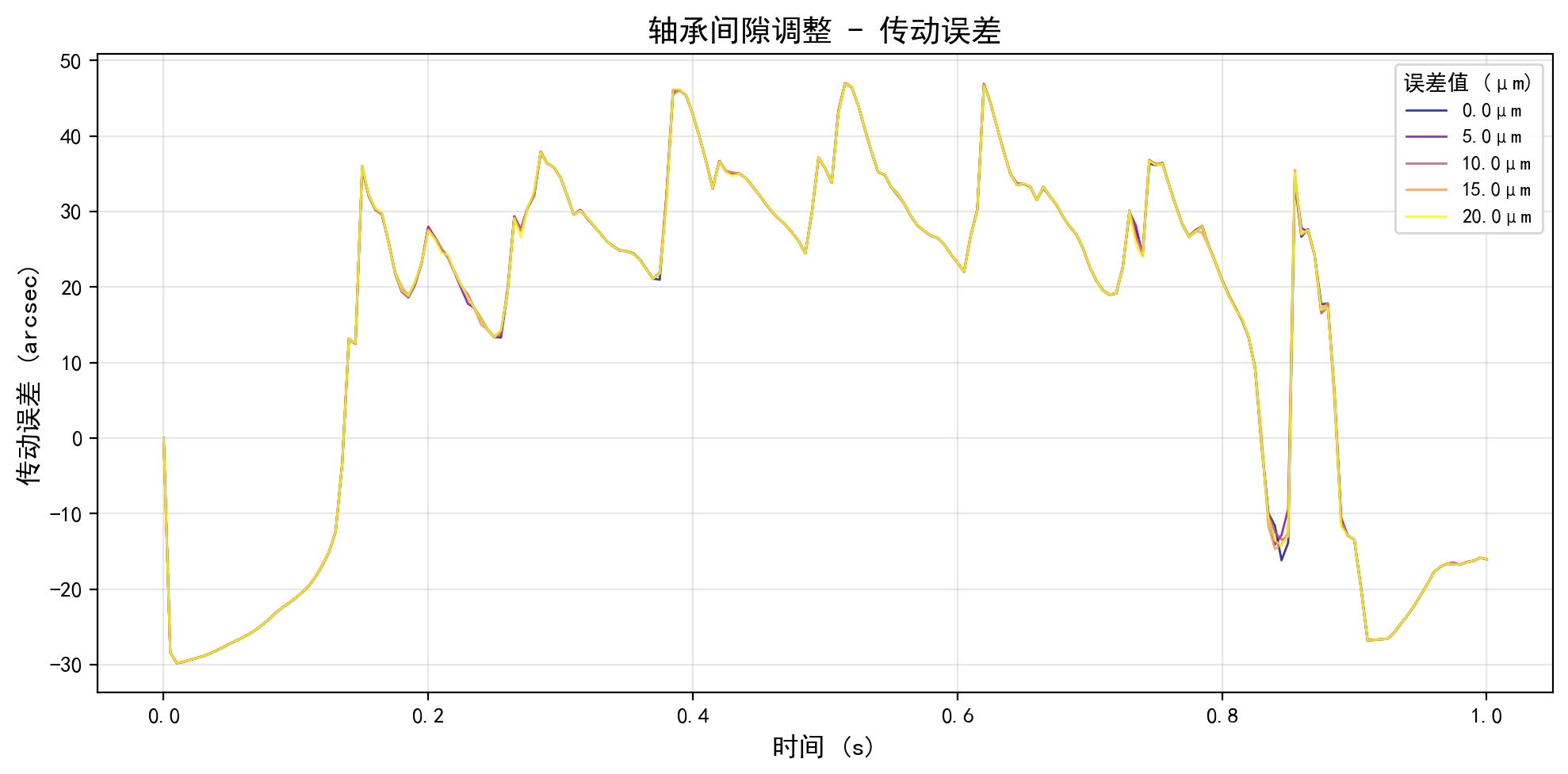
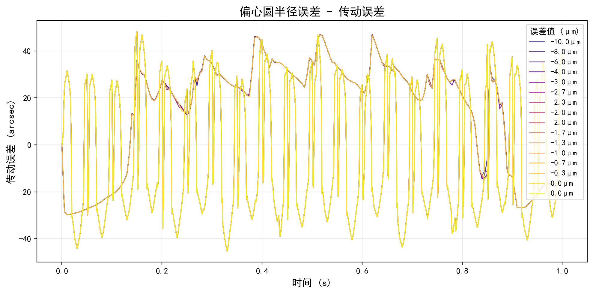
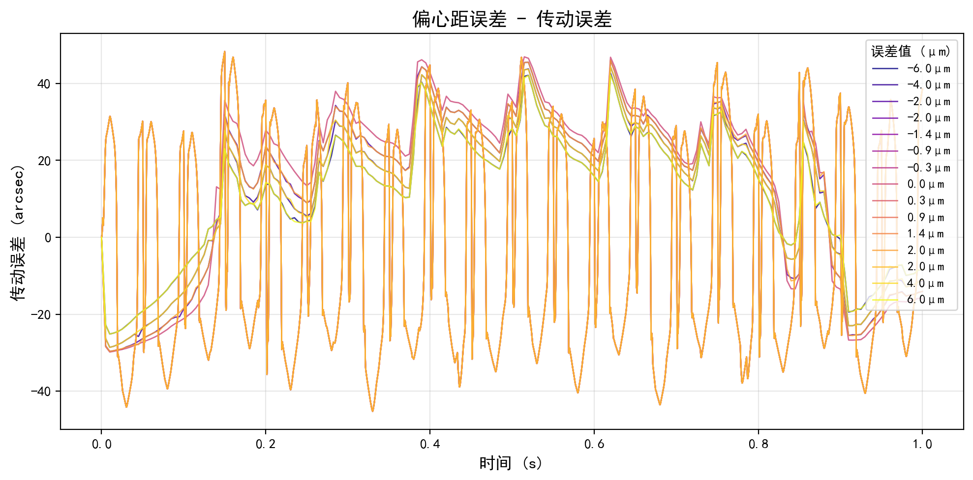
Figure 4: Transmission error characteristics under various error conditions.
The sensitivity of TE to mechanical error is found to correlate primarily with phase and radial clearance error, not with eccentricity, a conclusion supported by stator and experimental benchmarks.
Practical and Theoretical Implications
The toolkit provides a rigorous, high-fidelity simulation environment for transmission error, lost motion, and torsional stiffness in precision reducers—enabling three major directions:
- Transmission precision optimization: Rapid tolerance studies support design-for-manufacturing, GDT allocation, and assembly process validation.
- Robotic system dynamics and control: Accurate models of non-linearities, dead zones, and local compliance empower feedforward compensation and diagnostics in torque/position control loops.
- Reducer architecture innovation: The framework allows the rapid prototyping and validation of unconventional architectures (including those incorporating full flexible body effects or 3D surficial/geometric non-idealities).
In addition, methodology extension is plausible for harmonic/flexspline reducers (by introducing shell-element ANCF and curve-curve contact), hypoid/non-axisymmetric gears (via surface-surface contact modules), and friction/wear prediction (by integrating measured 3D topographies).
Conclusion
The presented toolkit integrates explicit probe-based contact geometry with modular, accelerated dynamics for high-DOF reducer simulation. It fills the gap between black-box FEA and overly simplified analytical models, offering a flexible, extensible, and computationally efficient platform for both academic research and industrial application. The strong numerical evidence for the dominance of bearing clearance aligns with both intuition and the state-of-the-art, while also providing quantitative bounds lacking in prior work.
Future developments will include GPU-accelerated surface contact, extension to full 3D flexibility, and extensive test-bench validation, positioning this toolkit as a key resource for the next generation of robotic powertrain research and engineering.
References
See (2604.02387) for the full methodological and empirical details, code structure, and referenced literature.

