- The paper demonstrates that a lifecycle simulation framework reveals deployable capacity constraints far beyond what static MW metrics indicate.
- It shows that distributed redundancy minimizes stranded power compared to block redundancy, proving crucial for high-density, AI accelerator deployments.
- The study highlights that pod-scale deployment and hardware upgrade cadences critically affect throughput, cost, and overall facility efficiency.
Quantifying Lifecycle-Efficient Power Delivery Hierarchies for AI-Centric Datacenters
Motivation: The Shift to Extreme Power Density
The paper "Designing Datacenter Power Delivery Hierarchies for the AI Era" (2605.16255) addresses the architectural and operational inflection point imposed on datacenter infrastructure by the rapid increase in AI accelerator power density. While historical norms for rack power (~20 kW) are superseded by modern accelerator deployments that already exceed 150 kW per rack, projections call for systems approaching or exceeding 1 MW per rack by 2027 (Figure 1).
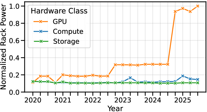
Figure 1: P99 of rack power density since 2020 for datacenter deployments, showing distinct accelerator generations and a widening gap between GPU and non-GPU power density. Density is normalized to the maximum P99 value observed in each quarter at Azure.
The paper establishes that such scaling invalidates traditional planning heuristics for datacenter electrical hierarchy, where total provisioned MW and CapEx per MW dominated design discussions. These static metrics fail as deployment units (racks/pods) become spatially and electrically coarser, and the actual deployable capacity over facility lifetimes becomes fundamentally constrained by interplays between resource partitioning, placement granularity, redundancy topology, and legacy design decisions.
Hierarchical Power Delivery: Topologies and Failure Modes
The canonical power-delivery hierarchy comprises grid/gen-set, transformers, UPS arrays, line-ups, busbars, and ultimately rack-level power conversion (Figure 2). Classical designs aim for high availability (e.g., Tier III/IV) by provisioning redundancy across the hierarchy; however, the structure of this redundancy (distributed versus block) critically determines the effectiveness of capacity utilization as power densities escalate.
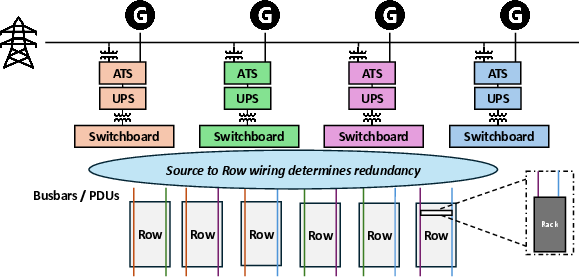
Figure 2: Example of major components in a datacenter power-delivery hierarchy, from grid and generator/battery down to the rack level.
- Distributed Redundancy (xN/y): Reserve capacity is spread across x active line-ups, each retaining fractional headroom for failover. As racks increase in power, successful placement requires that all requisite parents have simultaneous local headroom, leading to "reserve fragmentation".
- Block Redundancy (N+k): Active IT load is carried by N primaries, with k line-ups held in reserve. While this structure simplifies failover and maximizes headroom per block, it introduces "capacity quantization": once a deployment’s power plus fragmentation exceeds a block boundary, residual capacity is stranded and unusable.
Wire diagrams (Figure 3) illustrate these wiring paradigms.
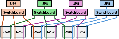
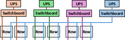
Figure 3: Schematic wiring differences between (a) distributed and (b) block redundant designs. Distributed designs keep reserve load on each UPS; block designs transfer load to a reserve UPS.
As deployment quanta (racks, pods) increase in size and heterogeneity, the probability that stranding occurs due to headroom fragmentation or quantization increases sharply. This paper analytically decouples these structural inefficiencies and quantifies their distinct signatures in both synthetic and Azure production-derived scenarios.
Modeling Approach: Lifecycle Simulation over Static Metrics
A core contribution is a lifecycle modeling and evaluation framework which simulates multi-year, multi-hall arrivals, harvesting/oversubscription, and retirements, under realistic workload (inference and training) mixes and hardware upgrade cadences. Rack-level resource vectors (electrical, thermal, spatial) are generated with time-dependent TDP projections (for GPUs, compute, storage; Figure 4). Placement heuristics (e.g., variance minimization) are evaluated for their ability to reduce stranding.
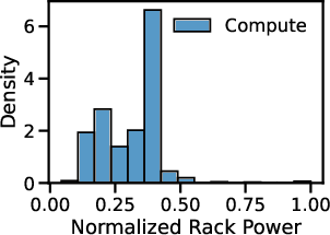
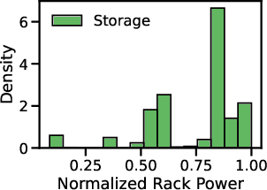
Figure 4: Normalized rack-power distributions for Azure general-compute and storage deployments since 2023, clustered for future trace generation.
Stranding is measured as the fraction of deployed, provisioned, but undeployable capacity at various hierarchy levels and projected over time. CapEx is tracked as both per-installed-MW and effective cost per deployed MW, exposing the latent cost of stranded capacity.
Validation against historical Azure hall deployment data shows the simulator closely matches empirical unused power distributions, establishing the model’s relevance for forward-looking design decisions (Figure 5).
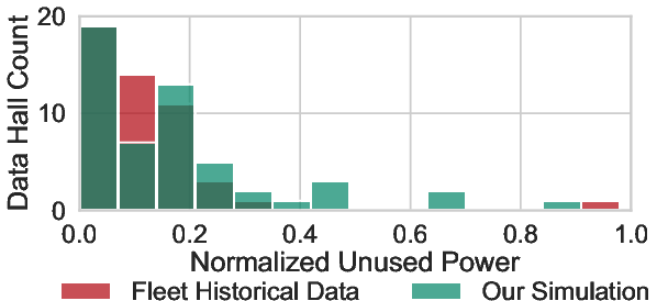
Figure 5: Validation of the simulator against historical rack placements in Azure over 6 years, comparing simulated and observed unused-power distribution.
Empirical Findings: Topology-Dependent Stranding and Cost Divergence
Static Provisioning Misleads; Dynamic Deployability Dominates
While static analysis and single-hall Monte Carlo sampling suggest small differences in stranding and cost across redundancy schemes (e.g., 4N/3, 3+1), full-fleet life cycle simulation reveals sharply divergent outcomes. Across 8 years, 3+1 block redundancy incurs high tail stranding, necessitating the construction of additional halls for identical deployed load (Figure 6).
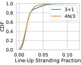
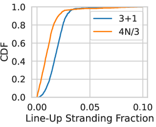
Figure 6: CDF of UPS stranding under (a) single-hall Monte Carlo analysis and (b) the final state of an 8-year fleet-scale lifecycle simulation.
Consequently, the effective cost per deployed MW grows considerably for block schemes. Under aggressive GPU TDP growth, block designs (3+1, 8+2) see cost increases dominated by stranding, not reserve per se (Figure 7).
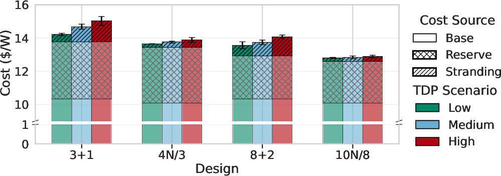
Figure 7: Incremental effective cost above each design's base \$/W. The main moving term is the cost of stranded capacity, not the nominal cost of reserve.
Quantitative Mechanistic Differentiation
The signature of stranding differs between redundancy classes. Block redundancy exhibits sharp capacity loss at divisibility thresholds associated with block size and deployment quantum (Figure 8), whereas distributed redundancy suffers from more continuous loss due to reserve fragmentation across multiple parents.
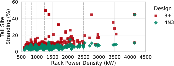
Figure 8: P90 tail stranding versus effective per-domain deployment power for 3+1 and 4N/3 across all GPU TDP scenarios and pod compositions.
Pod Deployment and Throughput/Cost Trade-Offs
For AI inference workloads (Mixture-of-Experts LLMs), larger pods improve intra-pod communication and inference throughput per watt, but at the cost of coarser placement granularity, hence higher stranding. The overall payoff (throughput/cost) depends not just on model size but crucially on the hierarchy’s capacity to admit larger quanta. Fine-grained distributed schemes (10N/8) better preserve this performance benefit at fleet scale than block schemes (8+2), where pod-induced coarseness more frequently triggers stranding (Figures 17, 18).
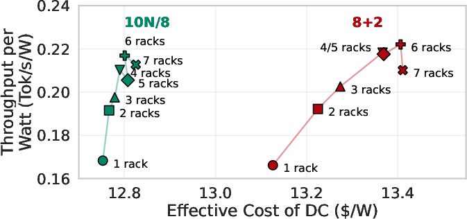
Figure 9: Effective fleet cost versus power-normalized throughput under High GPU TDP growth for MoE-132T.
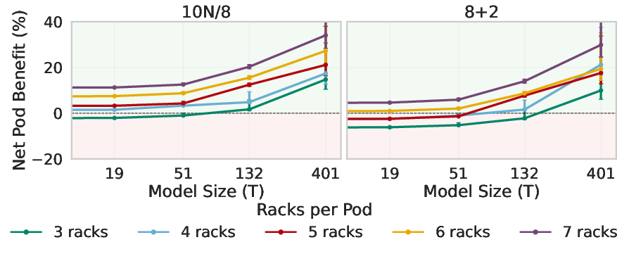
Figure 10: Pod payoff across model sizes for 10N/8 and 8+2. Only once communication benefit exceeds the deployability cost does pod payoff become positive; later crossover in block due to larger deployability penalty.
Operational Levers: Limited Recourse to Topological Constraints
Tuning operational parameters (e.g., deployment batch size, harvesting rates) offers marginal improvements in effective cost and stranding but cannot fundamentally alter the rankings or outcomes between redundancy classes (Figure 11). The hierarchy's structural constraints are first-order terms under high density and coarse-grained deployments.
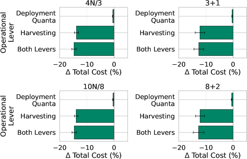
Figure 11: Change in total cost relative to the baseline fleet under the best setting from each operational lever family. Tuning yields only minor cost reductions and does not change design outcome rankings.
Practical and Theoretical Implications
The paper robustly demonstrates that datacenter power hierarchy evaluation for the AI era must shift from static installed MW/first-order CapEx calculus to lifecycle deployable capacity. Stranded power becomes the dominant effective cost as deployment quanta grow and topologies misalign with future hardware, with multi-billion-dollar cost impacts at hyperscale.
The work implies:
- Fleet-lifecycle simulation is essential for datacenter design decisions; static and even sophisticated single-hall modeling are inadequate.
- Distributed redundancy offers superior deployable capacity and effective cost at high power density, given its resilience to deployment quantum misalignment and quantization.
- Pod-scale deployment trade-offs are topology dependent, and over-investing in large pods may be suboptimal where hierarchy configuration is not matched to deployment scale.
- Operational tuning cannot substitute for topological alignment, and investments in effective placement policies offer diminishing returns when stranding is governed by hierarchy structure.
Speculation and Future Design Directions
As AI accelerator growth further distends the range and scale of rack power, next-gen facilities will require not only denser power distribution and cooling but also a fundamental rethinking of redundancy, row/busbar/UPS block sizing, and placement interfaces.
Theoretical directions include: joint optimization of electrical/mechanical/networking hierarchy for co-located high-bandwidth fabrics; dynamic re-partitioning or adaptive redundancy reconfiguration; and integration of real-time workload-driven admission control tightly coupled to electrical topology. Practically, hyperscale operators must prioritize modular designs admitting both fine and coarse grained deployments and embrace continuous, telemetry-driven re-evaluation of hierarchy deployability.
Conclusion
The results of this study underscore that, in the face of unprecedented power densities and deployment quanta associated with AI, the true datacenter design objective is maximized deployable capacity over time rather than installed nameplate MW. The dominant economic driver for next-generation AI datacenters will be the minimization of stranded power. Consequently, facility architects must rigorously account for how power delivery topologies interact with evolving hardware landscapes, placement history, and workload structures, making structural choices in the hierarchy a central systems constraint for effective scalable AI infrastructure (2605.16255).