- The paper demonstrates a novel contactless RF helicon plasma thruster that achieves over 99% electrical efficiency under VLEO conditions.
- It details an optimized specular-reflecting intake design that reaches up to 0.95 efficiency and maintains robust performance even with angular misalignments.
- Experimental results confirm stable operation on multiple propellants (Ar, N₂, O₂), meeting the drag compensation requirements for extended VLEO missions.
RF Helicon Plasma Thruster for Atmosphere-Breathing Electric Propulsion: Technical Summary and Assessment
Introduction and Context
Advances in satellite technology and the proliferation of commercial space activity have led to increased interest in very low Earth orbits (VLEO, h<450 km), where spacecraft benefit from enhanced observational capabilities and reduced radiation exposure. However, atmospheric drag at these altitudes critically limits mission duration, with orbital lifetimes spanning from months to days without active drag compensation. Traditional propulsion increases system mass due to propellant storage, thereby limiting mission flexibility.
Atmosphere-Breathing Electric Propulsion (ABEP) systems circumvent this limitation by ingesting and utilizing ambient atmospheric particles as propellant, enabling extended operations in VLEO without carrying onboard propellant. The present work details the design and development of a novel ABEP system, focusing on a radio-frequency (RF) helicon-based plasma thruster and accompanying intake architecture. The principal innovation lies in a contactless, neutralizer-free helicon discharge thruster, which offers high efficiency and broad propellant compatibility, paired with optimized particle intake devices for maximized collection efficiency.
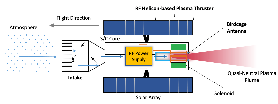
Figure 2: Schematic of an ABEP-equipped spacecraft employing the RF helicon-based plasma thruster.
ABEP System Analysis: Mission and System Dependencies
Power and Propulsion Requirements
ABEP performance is governed by the equilibrium between aerodynamic drag and provided thrust (D=T), directly linking power demand to environmental conditions, spacecraft geometry, and collection/thruster efficiencies. Notably, required electrical power for full drag compensation scales sublinearly with atmospheric density and orbital velocity, but is also a strong function of drag coefficient (CD), frontal area (Af), and the intake (ηc) and thruster (ηT) efficiencies:
Pin=81(CDAf)2v3(h)ρ(h)(AinηcηT1)
For VLEO operation, the principal atmospheric constituents are N2 and atomic oxygen. The latter introduces aggressive chemical environments that challenge conventional thruster materials, making contactless architectures and material selection critical.
Intake Design: Gas-Surface Interaction and Geometry Optimization
Intake Architectures
Three principal intake types were designed and analyzed, leveraging free molecular flow and gas-surface interaction (GSI) models:
- Diffuse-Reflecting Intakes: Utilize honeycomb ducts to maximize thermal accommodation. Achieved ηc<0.5. These designs are highly sensitive to alignment errors, with a >40% efficiency drop at misalignments of D=T0.
- Specular-Reflecting Intake: Employs parabolic, optics-inspired geometry to redirect incoming particles. Achieves D=T1 and demonstrates robust performance to misalignment, with only D=T2 efficiency drop at D=T3 misalignment.
- Hybrid Designs: Combine stages of specular and diffuse reflection for tunable pressure/flow regimes.
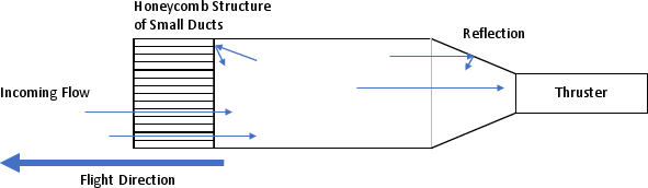
Figure 1: Diffuse-reflecting intake with honeycomb duct structure, designed for thermalization of incoming particles.
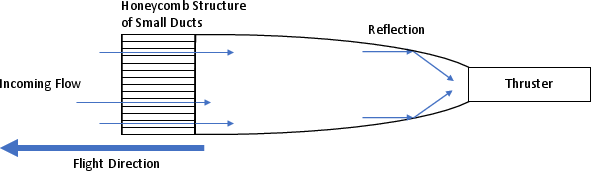
Figure 5: Specular-reflecting (parabolic) intake geometry for efficient particle redirection into the thruster.
Key Findings:
- Specular designs offer significant efficiency and robustness advantages, particularly for compact spacecraft with limited attitude stability.
- Material selection—such as HOPG and D=T4 coatings for specular walls, and Ti-alloys or gold coatings for diffusive surfaces—is pivotal for withstanding atomic oxygen erosion.
Thruster Development: RF Helicon Discharge and Birdcage Antenna
Technical Rationale
Atmospheric species in VLEO (notably atomic oxygen) rapidly erode conventional EP components (grids, channels, and neutralizers). To address this, the developed RF helicon thruster employs:
- Contactless Operation: No component is in direct plasma contact, mitigating AO-induced erosion and extending operational life.
- Propellant Flexibility: Capable of stable operation on D=T5, D=T6, and D=T7 at varying mass flow rates typical of VLEO intake conditions.
- No Neutralizer Requirement: The device inherently emits a quasi-neutral plasma jet.
Birdcage Antenna: Circuit and Plasma Coupling
The innovative application of a birdcage antenna—common in MRI applications—provides:
Experimental Results:
- Sustained operation on all tested propellants (CD2, CD3, CD4) with CD5 W and minimal reflected power. Stable ignition and operation was demonstrated across the ABEP-relevant flow envelope.
- High thruster electrical efficiency, exceeding CD6 under matched conditions (in the absence of plasma back-reaction).
- Output exhaust velocities (CD7) and propellant utilization match or exceed analytical requirements for full drag compensation at target altitudes for both Earth and Mars.
Intake–Thruster Integration and System Implications
Numerical and DSMC simulation, validated via prototype builds, confirm that:
- High intake efficiency, particularly in the specular design, translates directly to reductions in required electrical power and system mass.
- The contactless helicon thruster architecture maintains reliable operation across the spatial and compositional variability of VLEO, with no need for auxiliary neutralizing hardware.
Implications, Future Directions, and Theoretical Considerations
Practical Implications
The demonstrated ABEP system architecture enables:
- Extended orbital lifetimes in VLEO with no onboard propellant storage, directly addressing end-of-life and debris mitigation concerns.
- Application flexibility beyond Earth, to Mars (VLMO), Venus, Titan, and potentially gas giant atmospheres—provided sufficient electrical power.
- System scalability: intake and thruster modules can be clustered or distributed for larger spacecraft, or miniaturized for cubesat-class vehicles.
Theoretical and Technological Challenges
- Material selection for AO-resistant, high-fidelity GSI properties remains an open area requiring further in-orbit demonstration.
- Further plasma diagnostics (Langmuir, Faraday, three-axis B-dot probe) are required to conclusively quantify CD8, CD9, and helicon wave presence in the exhaust.
- Active impedance-matching and thermal management may be required for flight units to maintain performance over mission durations.
Conclusion
The presented RF helicon-based ABEP system substantially progresses atmosphere-breathing propulsion for VLEO applications by delivering:
- High intake collection efficiency (Af0 up to Af1 for specular), with low angular sensitivity;
- Contactless, highly efficient quasi-neutral plasma production via a resonant birdcage antenna (Af2 vacuum, Af3 W for ignition and sustained operation on all atmospheric species);
- Demonstrated feeder, antenna, and matching network design supporting robust operation with variable atmospheric density and composition;
- System modeling showing required Af4 and power output align with the thrust needs for drag compensation across a broad range of altitudes and planetary atmospheres.
These findings establish a solid foundation for future ABEP spaceflight demonstration missions and address most of the critical failure modes identified in earlier ground and conceptual studies. Further work will be directed toward comprehensive plasma diagnostics, AO-material interaction testing, and integrated intake-thruster unit optimization for sustained on-orbit operation.
Figure 2: Schematic of an ABEP-equipped spacecraft employing the RF helicon-based plasma thruster.
Figure 1: Diffuse-reflecting intake with honeycomb duct structure, designed for thermalization of incoming particles.
Figure 5: Specular-reflecting (parabolic) intake geometry for efficient particle redirection into the thruster.
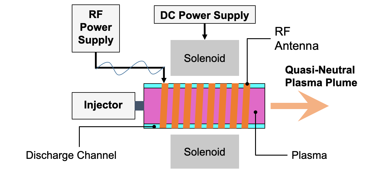
Figure 7: Conceptual diagram of the helicon plasma thruster with birdcage antenna, solenoid, and discharge channel.

