- The paper introduces a gradient-based GME inverse design that significantly enhances the cavity Q-factor and far-field mode overlap.
- It achieves a nearly 9,000 Q-factor with an 87% Gaussian mode overlap (NA = 0.68), outperforming traditional bullseye designs.
- The study confirms design robustness against ±6 nm fabrication variations, ensuring its practical viability in spin-photon interfaces.
Guided-Mode Expansion Inverse Design for Circular Cavity Optimization
Motivation and Context
Spin-photon interfaces enable the deterministic transfer of quantum information between stationary matter qubits and flying photonic qubits, which are central to quantum networking, distributed quantum computing, and measurement-based quantum protocols. Optimal spin-photon interfaces demand photonic cavities with high Q-factors, arbitrary polarization support, and efficient far-field optical access. Traditional approaches, such as periodic "bullseye" cavities, fall short by exhibiting low Q-factors (∼1,000) but a favorable Gaussian far-field profile, presenting a fundamental trade-off between Q-factor and collection efficiency. The paper addresses this challenge by leveraging gradient-based inverse design—guided-mode expansion (GME) with automatic differentiation—to engineer circular cavities with superior optical properties and polarization degeneracy.
Methodological Framework
The authors employ GME for electromagnetic field computation in circular cavities, circumventing the prohibitive computational costs of FDTD for parameter optimization. GME's frequency-domain formulation provides direct access to complex eigenfrequencies, yielding Q-factors in a computationally efficient fashion. The optimization targets three metrics: resonance frequency, Q-factor, and far-field mode overlap with a Gaussian profile mimicking a typical collection optic (NA = 0.68). The multi-objective loss function is constructed as:
L=1−wQ⋅τQ−wFF⋅τFF−wf⋅τf
where weights prioritize Q-factor, far-field overlap, and frequency proximity. The cavity geometry—central disk radius and widths of seven concentric air rings in a GaAs slab—is iteratively updated via gradient descent over 105 epochs, seeking simultaneous enhancement of Q-factor and collection efficiency.
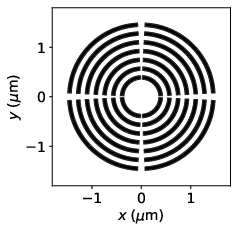
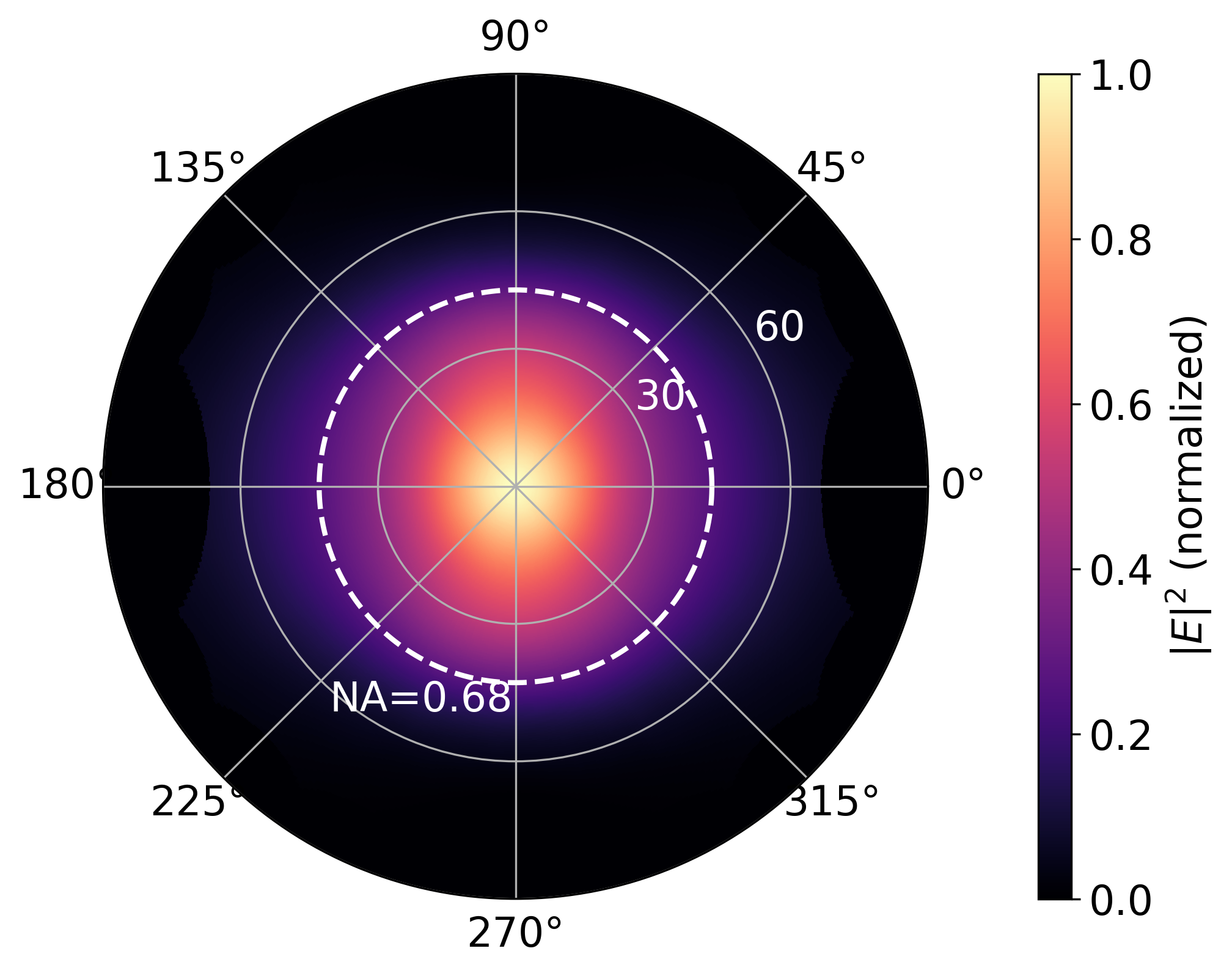
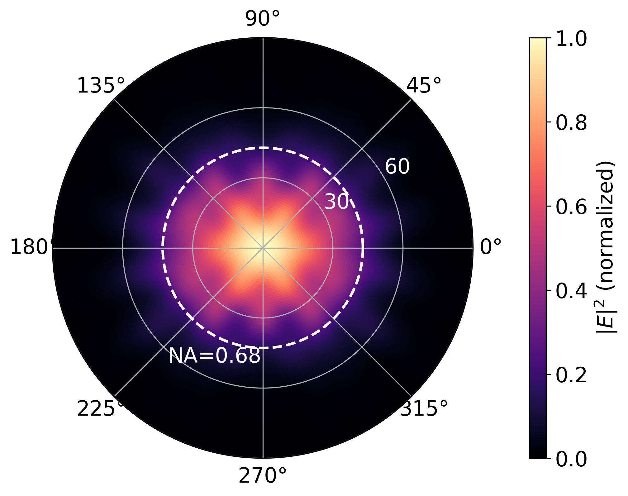
Figure 1: Comparison of periodic bullseye cavity geometry and far-field emission profiles computed via GME and FDTD.
Validation of the GME approach is established by benchmarking simulated Q-factor and far-field mode of a periodic bullseye cavity against FDTD results, showing Q=1,364 (GME) versus Q=1,212 (FDTD) and mode overlaps exceeding 94%. This motivates application of the method to inverse design.
Numerical Results and Analysis
The optimization procedure yields a non-periodic cavity with adjusted ring widths and central disk radius, achieving a calculated Q-factor ∼9,000—an order-of-magnitude increase over the periodic design—while preserving a Gaussian far-field emission with 87% mode overlap for NA = 0.68. GME results are corroborated by FDTD simulations, affirming the improved Q-factor and directionality, albeit with slight wavelength shifts due to geometric modification.
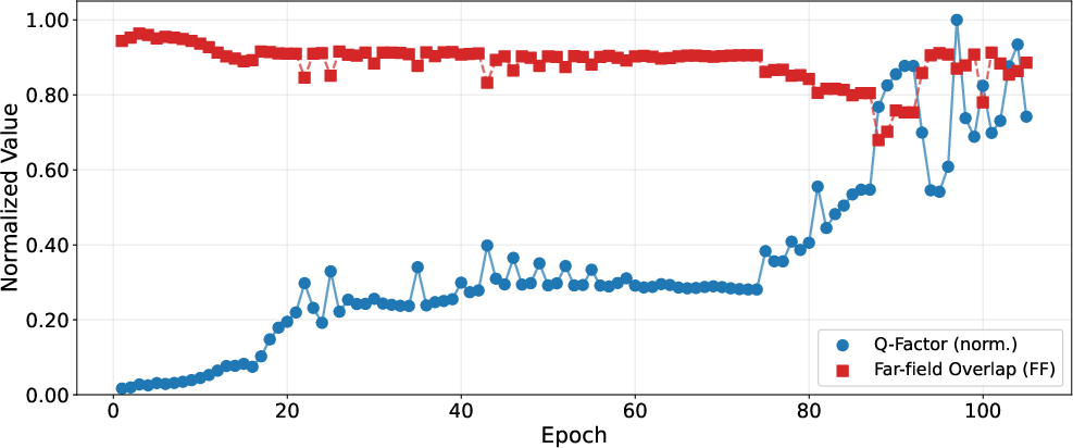
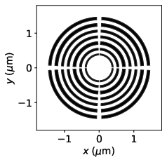
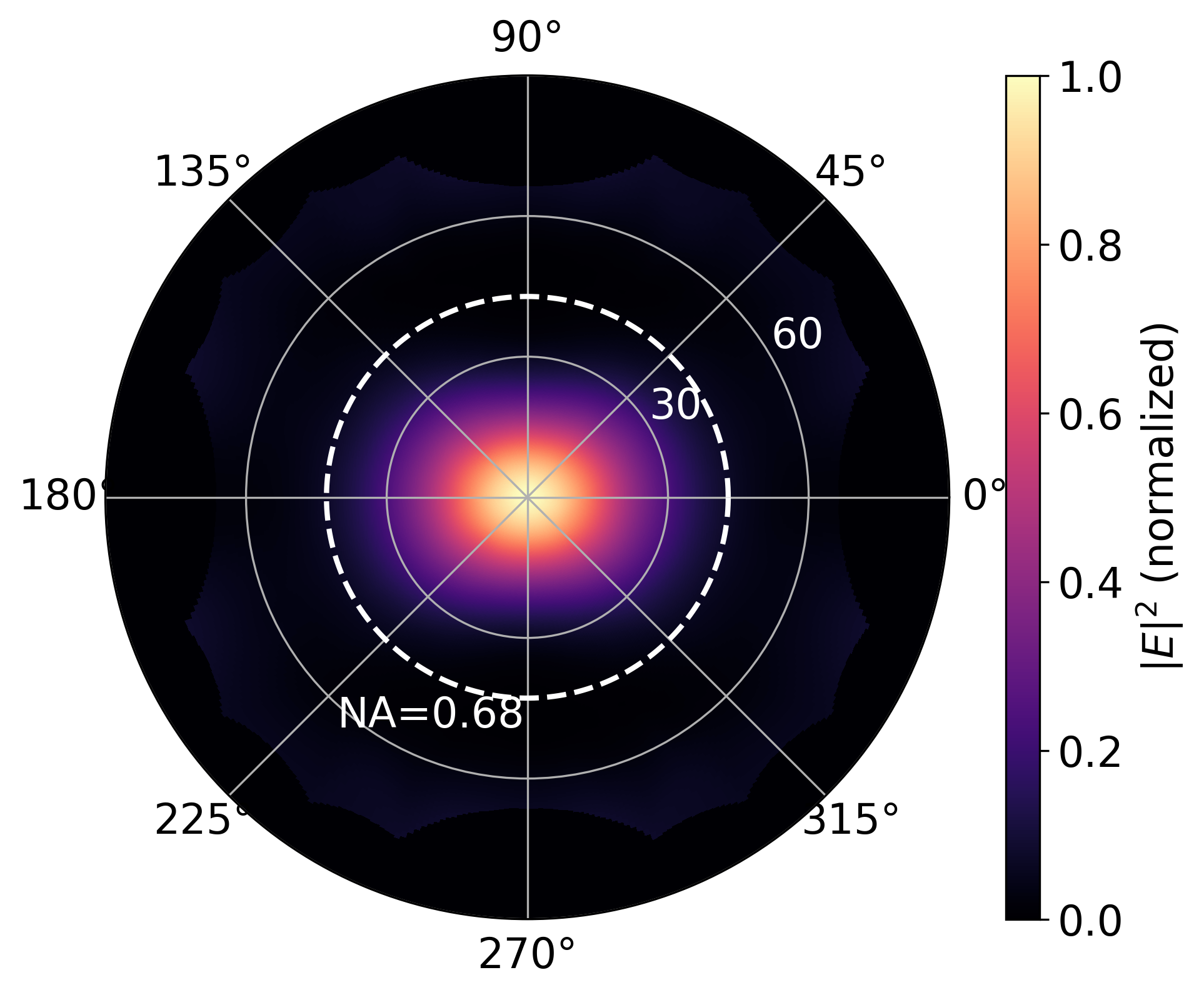
Figure 2: Evolution of Q-factor and far-field mode overlap across optimization epochs, final inverse-designed cavity geometry, and GME far-field emission pattern.
Collection efficiency as a function of NA reveals that the inverse-designed cavity outperforms the periodic bullseye up to NA ≈ 0.6, crucial for low-NA channels such as lensed fibers in quantum photonic hardware. Above this threshold, the periodic cavity marginally surpasses the inverse-designed cavity, converging to unity at NA = 1.
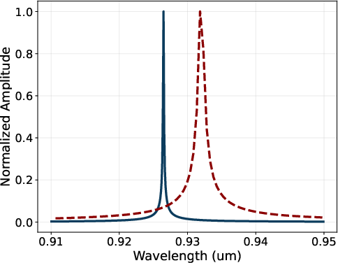
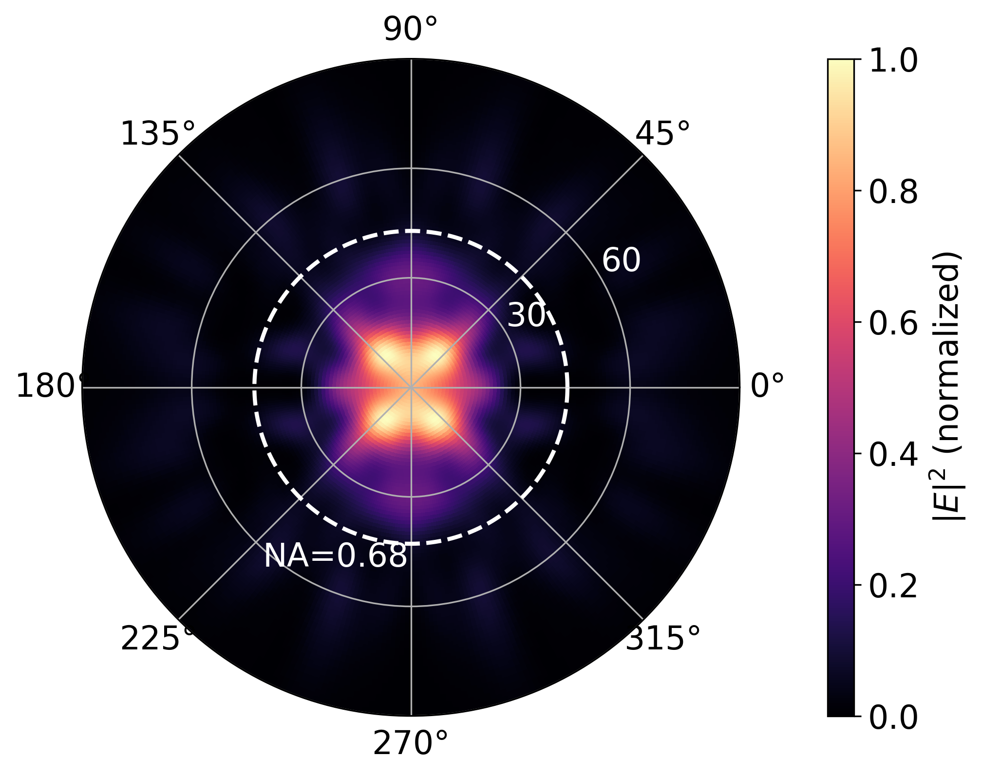
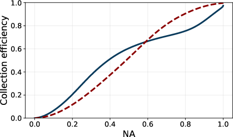
Figure 3: FDTD simulated resonance spectra, far-field pattern, and collection efficiency comparison between inverse-designed and periodic cavities.
A pivotal aspect of practical deployment—robustness to nanofabrication error—is quantified by varying geometric parameters ±6 nm. Sensitivity analysis reveals the innermost ring width and central disk radius as the most influential factors; a ±6 nm reduction in the first ring width boosts the Q-factor by up to 40% and collection efficiency by 45%. Overall, the inverse-designed cavity maintains favorable trade-offs under reasonable dimensional variation, suggesting practical resilience.
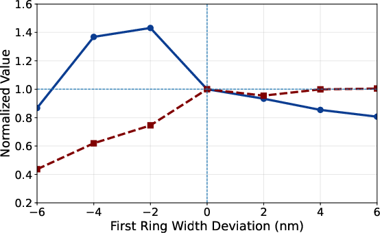
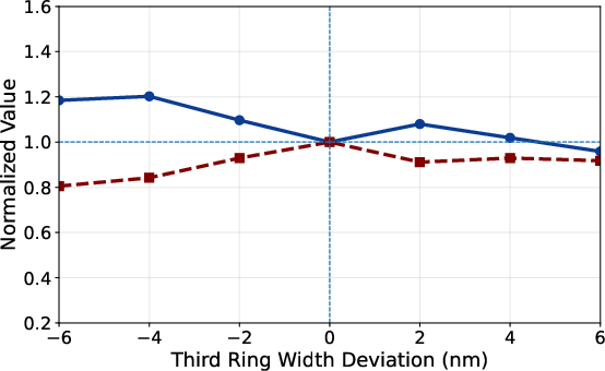
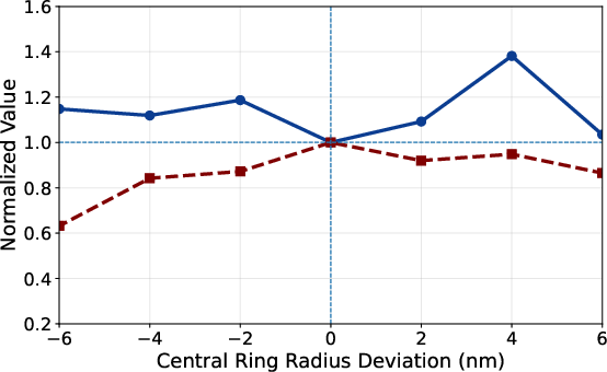
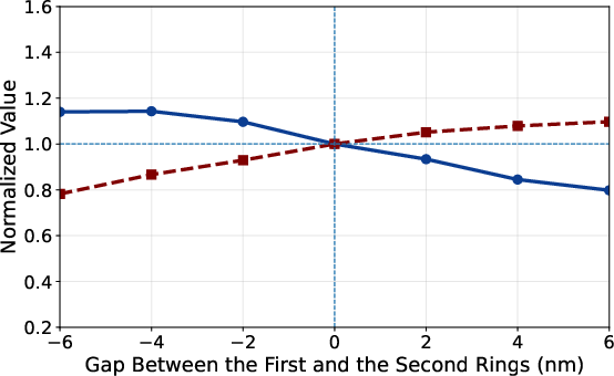
Figure 4: Single-parameter fabrication tolerance analysis showing trade-offs between normalized Q-factor and collection efficiency under dimensional deviations.
Implications and Future Directions
The GME-based inverse design framework provides a scalable, computationally tractable approach to co-optimizing cavity Q-factor and far-field emission in polarization-degenerate geometries. The demonstrated improvement in Q-factor and collection efficiency directly impacts the feasibility of high-cooperativity spin-photon interfaces, fundamental to deterministic photon entanglement and efficient quantum communication. While the study focuses on GaAs/InAs quantum dot platforms, the methodology is transferrable to other solid-state emitters, including NV centers and rare-earth ions, and adaptable to alternative cavity topologies.
Possible extensions include applying GME inverse design to cavities with etched holes or bridge-free support structures, and integration with advanced fabrication pipelines for deterministic quantum dot placement. The robust optimization protocol can further inform hybrid quantum photonic systems, enhancing photon indistinguishability and entanglement fidelity in networked architectures.
Conclusion
This paper establishes gradient-based GME inverse design as a powerful tool for engineering circular photonic cavities with arbitrary polarization, high Q-factor, and efficient far-field emission. The resulting structures deliver nearly an order-of-magnitude enhancement in Q-factor over traditional bullseye designs, with practical resilience to fabrication tolerances. The approach advances the state of cavity optimization for high-cooperativity spin-photon interfaces, promising broader adoption in quantum photonic device engineering and scalable quantum networking.