Cerberus: Cross-Layer ECC Co-Design for Robust and Efficient Memory Protection
Abstract: As DRAM scales to higher density and I/O speeds, ensuring data correctness becomes increasingly difficult. Industry has responded with a three-layer stack: on-die ECC (O-ECC), link ECC (L-ECC), and system ECC (S-ECC). However, these layers have evolved independently, often duplicating redundancy, leaving coverage gaps, and occasionally interfering. We propose Cerberus, a cross-layer ECC co-design that unifies protection across device, link, and system while preserving the native role of each layer. At its core is an Encode-Once, Decode-Many (EODM) architecture: the controller performs a single encoding whose redundancy is reused by L-ECC for immediate write-path detection and retry, by O-ECC for in-device repair on reads, and by S-ECC for strong end-to-end recovery. Cerberus jointly designs complementary parity and syndrome structures, orders decoders, and allocates the correction budget to prevent miscorrection amplification and enable selective correction under tight redundancy constraints. Our evaluations show improved resilience to clustered and peripheral faults while reducing redundant overhead, underscoring the importance of coordinated cross-layer protection for next-generation memory systems, such as custom HBMs.
Paper Prompts
Sign up for free to create and run prompts on this paper using GPT-5.
Top Community Prompts
Explain it Like I'm 14
Explaining “Cerberus: Cross-Layer ECC Co-Design for Robust and Efficient Memory Protection”
What is this paper about?
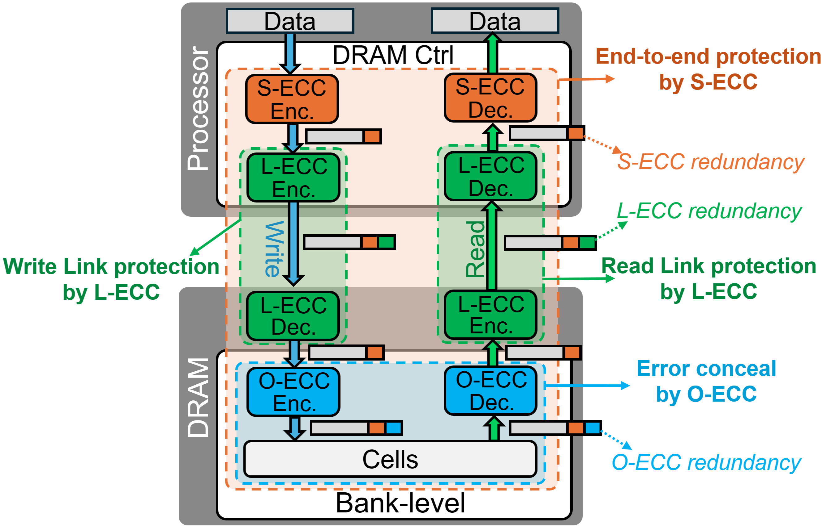
Computers store huge amounts of data in memory chips (like DRAM). As these chips get faster and pack more bits into tiny spaces, they make more mistakes—flipped bits or chunks of data getting corrupted. To catch and fix these mistakes, engineers add “extra check bits” called ECC (Error-Correcting Codes). Today, memory uses three separate ECC layers:
- Inside the chip (On-die ECC, or O‑ECC)
- On the wires between the chip and the processor (Link ECC, or L‑ECC)
- At the processor side (System ECC, or S‑ECC)
The problem: these three layers were designed separately. They sometimes repeat the same work, leave gaps, or even get in each other’s way. The paper proposes “Cerberus,” a smarter, coordinated way to make all three layers work together smoothly and more efficiently.
Think of Cerberus as three guard dogs (like the mythical three-headed Cerberus) that finally learn to protect the same gate as a team instead of barking over each other.
What questions is the paper trying to answer?
- How can we make the three ECC layers share information so they don’t waste extra bits or miss errors?
- Can we reuse the same “extra check bits” across layers instead of creating new ones each time?
- How do we prevent a wrong fix (called a “miscorrection”) in one layer from making things worse for the others?
- Can we keep strong protection even when there’s only a small space for ECC (common in fast memories like HBM and LPDDR)?
How did the researchers approach the problem?
They introduced a design called Encode-Once, Decode-Many (EODM). Here’s the idea in everyday terms:
- Imagine putting a single, smart stamp on a package before shipping it. That one stamp can be checked by:
- The mail truck driver (L‑ECC) to catch problems on the road and ask for a quick resend if needed,
- The local post office (O‑ECC) to repair small damage that happened inside the building,
- The final receiver (S‑ECC) to do a strong, end-to-end check and fix anything left.
Instead of creating three different stamps (one per layer), Cerberus creates one shared “stamp” (ECC encoding) that all layers can read and use in their own way. This saves space and avoids conflicts.
To make this work, the paper:
- Carefully co-designs the math behind ECC (the “generator” and “parity-check” matrices) so every layer’s checks fit together like puzzle pieces.
- Sets a safety rule (a “bounded-fault” constraint) so if a lower layer guesses wrong, the damage stays inside a tiny region—small enough for the higher layer to fix. Think of it as putting a fence around any mistake so it can’t spread.
- Decides the right order for who checks first and how much “fixing power” each layer gets, so they don’t step on each other’s toes.
- Keeps each layer’s job: O‑ECC fixes chip-internal issues, L‑ECC quickly detects link glitches and retries, and S‑ECC guarantees the final, end-to-end correctness.
What did they find, and why does it matter?
Using Cerberus, the system becomes both tougher and leaner. According to the paper’s evaluation:
- It handled tough error types better, including “clustered” errors (many nearby bits breaking at once) and “peripheral” faults (problems near the chip’s supporting circuits or on the interconnects).
- It used less storage for ECC. In an HBM-like setup, Cerberus reduced ECC storage overhead by about 33.3% yet still increased overall reliability.
- With the same ECC budget as LPDDR6, Cerberus provided much stronger protection.
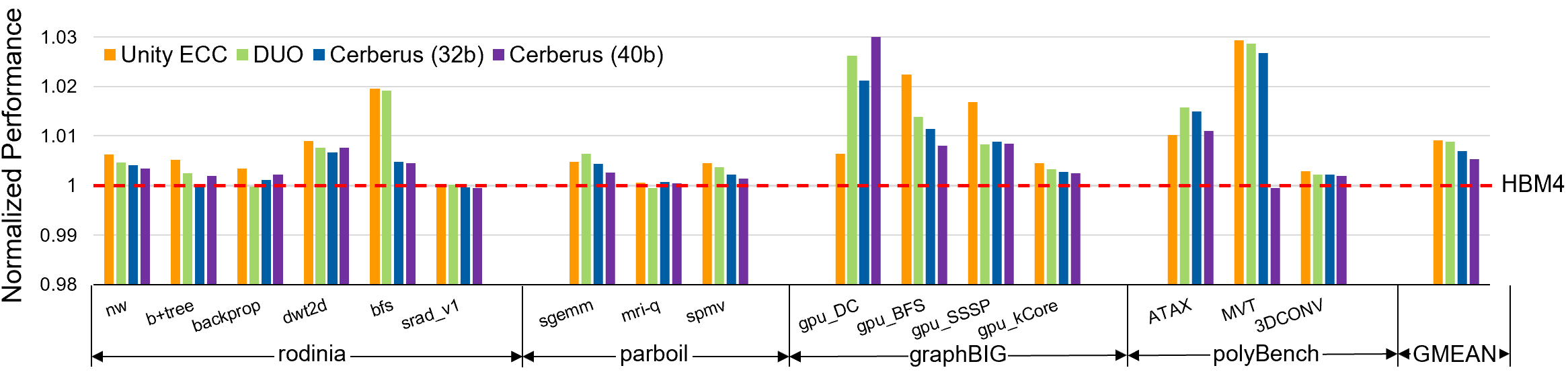
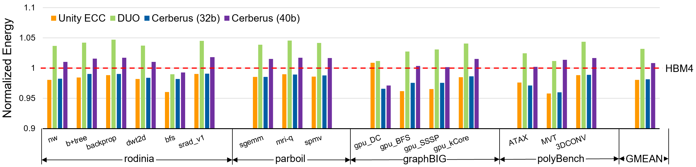
- It slightly improved performance (about 0.7%), mainly by avoiding multiple, separate encoding steps.
Why this matters: as chips get faster and denser, errors are more likely to come in bursts or from tricky places the old methods don’t cover well. Cerberus catches more of these without needing extra space or time.
What’s the bigger impact?
Cerberus shows that coordinating ECC across layers is better than treating them as separate silos. This can:
- Make future high-speed memories (like HBM in AI accelerators and LPDDR in phones) more reliable without adding a lot of cost or power.
- Reduce the chance of silent data corruption—wrong answers that slip by unnoticed—which is the most dangerous kind of error.
- Improve manufacturing yield (more chips pass quality checks) because on-chip fixes are smarter and don’t create trouble for the system later.
- Provide a practical blueprint that different companies (processor and memory vendors) can adopt since it respects each layer’s original job while making them work as a team.
In short, Cerberus turns three separate safety nets into one coordinated safety system—catching more problems, wasting fewer bits, and keeping our data safer as memory technology keeps pushing the limits.
Knowledge Gaps
Knowledge gaps, limitations, and open questions
Below is a concise, actionable list of what remains missing, uncertain, or unexplored based on the paper’s description of Cerberus and its motivation.
- Formal code construction details: the paper proposes co-designing generator/parity-check matrices with reuse across layers and a bounded-fault (BF) constraint, but does not specify concrete code families, construction algorithms, or parameterized templates (e.g., for different symbol widths, beat lengths, or interleaving schemes), nor provide formal proofs of correction/detection guarantees and miscorrection bounds under these constructions.
- BF enforcement for single-device channels: the paper argues for BF-like behavior in HBM/LPDDR O-ECC, yet leaves open a practical design that enforces BF within existing HBM/LPDDR device microarchitectures, including how boundaries map to internal peripheral structures and how to align boundaries with S-ECC symbols without constraining vendor layouts or harming yield.
- Interoperability and standardization: EODM implies controller-generated redundancy must be consumable by on-die decoders. The paper does not specify required JEDEC interface changes, metadata formats, syndrome exchange mechanisms, or negotiation protocols to ensure controller–device interoperability across vendors and generations.
- Device-side architectural changes: the feasibility of modifying O-ECC to consume externally stored/shared redundancy (vs private, hidden redundancy) is not addressed, including impacts on DRAM die area, routing, timing margins, and test flows if O-ECC depends on codewords written by the controller.
- Backward compatibility and deployment path: the paper lacks a migration plan for systems with legacy devices that implement opaque O-ECC, including fallback modes, mixed-population operation (Cerberus vs non-Cerberus stacks), and software/firmware changes needed to enable EODM incrementally.
- Read-path link protection semantics: the paper mentions read-side L-ECC but does not specify how read retransmission or correction is orchestrated in DRAM protocols that historically lack robust read retry. Open items include replay window sizing, NACK signaling, deadlock avoidance, and throughput impact under elevated BER.
- Quantitative reliability across real fault spectra: claims of improved resilience to clustered and peripheral faults lack comprehensive SDC/DUE rate quantification across diverse, empirically grounded fault models (e.g., TSV/interposer faults, global I/O, SWD/SWL faults, VRT, aging-related intermittency), including tail-risk analysis and comparison to field data.
- Evaluation methodology transparency: details on fault injection models, correlation structures, parameter sweeps (burst sizes, symbol widths), workload representativeness, and statistical confidence intervals are not provided, limiting reproducibility and external validation.
- Latency, area, and power overheads: while the paper cites a 0.7% performance gain, it does not quantify controller/DRAM encode/decode critical paths, decoder complexity (especially “decode-many” concurrency), area/power costs for matrix co-design, or energy/latency trade-offs under worst-case correction workloads.
- Impact on manufacturability and yield: how EODM and BF constraints interact with the primary O-ECC role (yield enhancement) is not analyzed. Open questions include whether BF constraints reduce the class of repairable die-side faults, change binning criteria, or require additional redundancy cells.
- Runtime policy for “selective correction” and budget allocation: the paper references selective correction and correction-budget ordering but lacks algorithms/policies for deciding which layer should correct vs detect under evolving error conditions, and how to adapt code parameters online with changing BERs or aging.
- Partial writes and read-modify-write (RMW) semantics: with “encode-once” redundancy shared across layers, it is unclear how partial-line writes, sub-beat updates, or cache-line merges are supported without violating codeword consistency, and what additional RMW traffic or hazards ensue.
- Symbol/boundary mapping robustness: the paper does not address how ECC symbol boundaries stay aligned with physical DQ/beat mapping under scrambling, lane remapping, interleaving, or TSV sparing, nor how misalignment affects BF guarantees and S-ECC symbol-level recovery.
- Telemetry and diagnosability: cross-layer visibility is cited as a goal, but the design does not define what syndromes/metadata are exposed, how error provenance (link vs device vs array) is reported to software, or how to avoid privacy/IP concerns while enabling actionable telemetry.
- Read-disturb/rowhammer and VRT coverage: the impact of EODM on disturbance-induced or retention-induced multi-bit patterns is not evaluated, including whether code parameters or boundary definitions need tuning to handle temporally clustered events and whether scrubbing policies should be co-designed.
- Interaction with DBI, in-line compression, and encryption: LPDDR6 multiplexes EDC/DBI; the paper does not clarify how Cerberus coexists with DBI, compression, or memory encryption (e.g., where to place ECC relative to cipher/codec) and what error propagation or misdetection risks arise.
- Handling of severe link or TSV faults: while end-to-end robustness is claimed, the paper does not specify maximum tolerable persistent link/TSV fault counts per codeword, the interplay with lane sparing/remapping, or policies for transitioning from retry to hard-fault containment.
- Protocol-level flow control under error bursts: there is no analysis of retry storms, queueing, and QoS under bursty link errors when L-ECC triggers retransmissions, nor of buffer sizing, timeouts, and fairness across pseudo-channels.
- Generalization to other granularities and systems: the approach is motivated for 32B SDPC systems; it remains unclear how to parameterize Cerberus for 64B or larger line sizes, different burst lengths, multi-device DDR ranks, or NVRAM/3D-stacked variants with different error topologies.
- Design automation for co-optimized matrices: the paper does not provide tools or methods to synthesize
G/Hthat satisfy reuse, BF constraints, and heterogeneous symbol organizations, nor benchmarks to compare constructions (e.g., SSC+DEC vs BCH/RS hybrids) under fixed redundancy budgets. - Software interface and recovery: beyond hardware correction, system-level handling of DUEs (poisoning, page offlining, retirement policies, logging) under Cerberus is unspecified; the software-visible error model may change when lower layers correct selectively.
- Long-term aging and environmental shifts: adaptive reconfiguration (e.g., symbol size, correction budgets, scrubbing cadence) as devices age or operate across temperature/voltage corners is not discussed, nor are triggers and safety mechanisms for dynamic policy changes.
- Security implications: the paper does not consider adversarial fault injection, side channels via error telemetry, or interactions with integrity-tag schemes; it is unclear whether EODM’s shared redundancy introduces new attack surfaces or complicates tamper detection.
- Failure-mode isolation and root-cause attribution: with shared redundancy, separating link-induced vs device-induced errors for RMA/field diagnostics remains an open question; required counters, timestamps, and correlation techniques are unspecified.
- Standard and test impacts: required changes to bring-up, training, margining, BIST, and production test to validate cross-layer codes and BF properties are not addressed, including how to certify SDC rates with shared redundancy across layers.
Practical Applications
Cerberus proposes a cross-layer ECC co-design for DRAM that unifies on-die (O-ECC), link (L-ECC), and system (S-ECC) protection via an Encode-Once, Decode-Many (EODM) architecture, bounded-fault (BF) constraints to prevent miscorrection amplification, and co-designed generator/parity-check matrices to reuse one redundancy pool across layers. The result is higher resilience to clustered/peripheral faults with lower parity and transfer overhead, demonstrated for single-device-per-channel (HBM/LPDDR) configurations.
Below are actionable, sector-linked applications derived from the paper’s findings, grouped by deployment horizon. Each item notes potential tools/products/workflows and assumptions/dependencies that affect feasibility.
Immediate Applications
These can be piloted or deployed now in vertically integrated products, custom SoCs, or through configuration/firmware choices in existing platforms.
- Cerberus-enabled HBM controllers for AI/ML accelerators (semiconductors, AI hardware, HPC)
- What it enables: Integrate EODM in the memory controller and apply BF-aware O-ECC to improve reliability against 8–32-bit clustered faults while reducing parity/transfer overhead compared to ad-hoc multi-layer ECC stacks.
- Tools/products/workflows: Cerberus-ready memory-controller IP (EODM encoder, decoder ordering, selective correction); BF-compliant O-ECC matrix synthesis; PHY replay for L-ECC-based write-path detection/retry; RTL regression and fault-injection testbenches reflecting clustered/peripheral fault models.
- Assumptions/dependencies: Requires controller–HBM vendor collaboration to co-design matrices and agree on redundancy format; relies on JEDEC-compliant private modes or custom HBM stacks; area/power headroom for modified ECC datapaths; fault model alignment (cluster width up to ≈16 bits per access typical in modern DRAM).
- LPDDR6 SoCs with unified redundancy reuse and BF O-ECC (mobile, AR/VR, consumer electronics)
- What it enables: Reuse a single 16-bit redundancy budget across L-ECC/O-ECC/S-ECC to improve field reliability with minimal bandwidth/power cost; adopt CRC at S-ECC under tight budgets to minimize SDC risk in SDPC channels.
- Tools/products/workflows: Controller firmware/RTL to implement EODM and decoder ordering; BF O-ECC code selection at die design; PHY support for link detection and replay; validation using VRT/row-hammer/peripheral-fault stress patterns.
- Assumptions/dependencies: Must fit within LPDDR6 pin/burst constraints; requires DRAM vendor support for BF-compliant O-ECC matrices; limited by existing L-ECC/DBI slotting in subchannel transfers.
- Reliability uplift in safety-critical memory subsystems (automotive, industrial/robotics)
- What it enables: Higher diagnostic coverage and reduced SDC through cross-layer coordination and BF-constrained miscorrections, supporting ISO 26262 safety cases with lower ECC overhead.
- Tools/products/workflows: Cross-layer error telemetry and logging (syndrome sharing or error-class tags), “ECC health monitor” firmware, safety analysis artifacts (FMEDA) using bounded-fault guarantees; production tests emulating peripheral/TSV faults.
- Assumptions/dependencies: Requires safety certification evidence for BF property and end-to-end detection rates; secure handling of syndrome metadata; supplier agreements for device-internal ECC behavior disclosures.
- HBM deployment tuning via ECC-mode selection (cloud/data centers, HPC)
- What it enables: Immediate reduction in SDC exposure by preferring CRC-based S-ECC in HBM4-like configurations where S-ECC parity is constrained, while maintaining O-ECC for on-die repair and L-ECC for write-path checks.
- Tools/products/workflows: Firmware/BIOS knobs to choose S-ECC profile (CRC vs SEC-DED) per workload; fleet monitoring dashboards tracking DCE/DUE/SDC rates; operational runbooks for link retry thresholds and scrub policies.
- Assumptions/dependencies: Hardware support for multiple S-ECC profiles; alignment with vendor guidance (e.g., HBM CRC misdetection probabilities); retraining and replay latency budgets.
- Yield and RMA reduction via BF-aware O-ECC in manufacturing (semiconductors)
- What it enables: Ship marginal dies by preventing miscorrection amplification across layers; improve effective yield with on-die local repair tuned to likely clustered faults.
- Tools/products/workflows: ATE patterns for clustered/peripheral faults; “bounded-fault checker” for O-ECC H-matrix design; binning criteria that exploit BF behavior and EODM compatibility.
- Assumptions/dependencies: Changes at DRAM die design (O-ECC logic, spare cells) and test flows; potential mask/IP updates; confidentiality/IP constraints around O-ECC matrices.
- Cross-layer error localization in bring-up and field diagnostics (semiconductors, systems)
- What it enables: Faster root-cause analysis by correlating link detections, O-ECC correction/detection outcomes, and S-ECC syndromes under a unified redundancy scheme.
- Tools/products/workflows: Cross-layer telemetry API; syndrome-to-physical-domain mapping tools (pin/MAT/TSV); error heatmaps; automated RMA triage workflows.
- Assumptions/dependencies: Minimal metadata exposure from the device (e.g., encoded severity or symbol-domain hints) without leaking IP; firmware and driver integration.
- Research and teaching platforms for cross-layer ECC (academia)
- What it enables: Reproducible studies on EODM, BF coding, decoder ordering, and selective correction trade-offs using realistic DRAM error models.
- Tools/products/workflows: Extensions to DRAMSim/DRAMSys/gem5; open-source matrix compilers for BF-compliant O-ECC and EODM-compatible S-/L-ECC; fault-injection harnesses reflecting 8–32-bit clusters and TSV/link errors.
- Assumptions/dependencies: Availability of open models/datasets or synthetic generators consistent with published studies; permissive licensing for code/IP.
Long-Term Applications
These require further research, standardization, silicon changes, or ecosystem-wide coordination.
- JEDEC standardization of cross-layer ECC semantics (policy/standards, semiconductors)
- What it enables: Portable EODM fields, decoder ordering rules, BF constraints, and optional syndrome-sharing metadata across vendors; explicit link-detect/replay guarantees.
- Tools/products/workflows: Standards track proposals for HBM5+/LPDDR7; interoperability test suites; conformance tools for BF property and miscorrection bounds.
- Assumptions/dependencies: Broad vendor buy-in; IP-safe ways to expose minimal-but-sufficient error-class metadata; backward compatibility modes.
- Cerberus-native HBM5/LPDDR7 devices and controllers (semiconductors, AI hardware, mobile)
- What it enables: Full-stack adoption with shared redundancy across layers, selective correction, and coordinated parity budgets tailored to SDPC constraints and new fault modes.
- Tools/products/workflows: Co-optimized DRAM die O-ECC, controller S-/L-ECC, and PHY link protection; EODM-aware training/replay protocols; silicon validation with clustered/TSV/interposer fault campaigns.
- Assumptions/dependencies: Process/power budgets for ECC logic; TSV/interposer reliability targets; evolving I/O rates and burst structures.
- Adaptive ECC budgets and runtime policy orchestration (cloud/data centers, HPC, mobile)
- What it enables: Dynamically allocate correction budget across layers (e.g., switch S-ECC profile, adjust replay windows, enable/disable selective correction) based on observed error spectra, workload sensitivity, or thermal/aging signals.
- Tools/products/workflows: “ECC Orchestrator” firmware; telemetry-driven control loops; per-application ECC profiles (e.g., LLM training vs inference); SLA-aware reliability knobs.
- Assumptions/dependencies: Rich error telemetry and safe-mode switches; closed-loop stability analysis; performance isolation.
- Cross-layer ECC for chiplets/CXL memory and in-package optics (semiconductors, data centers)
- What it enables: Extend EODM and BF concepts across die-to-die links (UCIe), CXL-attached memory, and optical interconnects to maintain end-to-end integrity across heterogeneous fabrics.
- Tools/products/workflows: Unified redundancy fields traversing chiplet boundaries; PHY-level detection with replay; fabric-wide syndrome correlation.
- Assumptions/dependencies: Multi-vendor fabric cooperation; latency constraints on replay; symbol alignment across different link widths and clocking domains.
- Storage-class and non-volatile memory co-design (storage, embedded)
- What it enables: Apply EODM to share redundancy between flash/NAND page ECC, channel coding, and system-level protection to cut overhead while improving SDC rates for SSDs or persistent memory.
- Tools/products/workflows: Controller firmware/RTL changes for shared syndromes; BF-inspired page/wordline locality constraints; validation under program/erase and retention-induced clustered errors.
- Assumptions/dependencies: Media-specific error physics; performance/QoS impact of link-level replay; compatibility with existing FTLs.
- Formal synthesis and verification of BF-compliant codes (EDA, academia)
- What it enables: Automated construction of parity-check matrices that provably enforce BF regions aligned to physical domains (pins/MATs/bank-groups) and guarantee non-amplifying miscorrections.
- Tools/products/workflows: “BF code compiler” EDA tool; SAT/SMT-based verification of miscorrection bounds; libraries of EODM-compatible generator/parity-check matrices.
- Assumptions/dependencies: Scalable solvers for large codes; integration into vendor EDA flows; proofs accepted by safety/quality auditors.
- Security and fault-attack resilience via cross-layer telemetry (security, automotive/industrial)
- What it enables: Detect and localize induced faults (e.g., EM/voltage/laser) through inconsistent cross-layer syndromes; trigger containment or safe-state transitions.
- Tools/products/workflows: Anomaly detection models on syndrome streams; security policies tied to ECC anomaly thresholds; secure logging pipelines.
- Assumptions/dependencies: Access to timely telemetry; mitigation paths that preserve safety and availability; low false-positive rates.
- Energy and TCO optimization from reduced parity/transfer overhead (cloud/mobile, sustainability)
- What it enables: Lower IO toggles and fewer retransmissions; modest performance gains (e.g., ≈0.7% reported) and energy savings that scale fleet-wide.
- Tools/products/workflows: Energy modeling for ECC configurations; procurement specs that factor ECC overhead into TCO; green-compute reporting tied to reliability settings.
- Assumptions/dependencies: Measurable savings under real workloads; no regression in target FIT/SDC rates; alignment with performance SLAs.
- Procurement and compliance frameworks emphasizing end-to-end integrity (policy, enterprise IT)
- What it enables: Contracts and SLAs that specify cross-layer detection/correction targets, miscorrection bounds, and telemetry availability rather than per-layer parity counts.
- Tools/products/workflows: RFP templates; compliance test suites; incident reporting formats based on DCE/DUE/SDC taxonomy.
- Assumptions/dependencies: Vendor transparency; standardized metrics; auditable test procedures.
- Curriculum and benchmarking for cross-layer memory reliability (academia, consortia)
- What it enables: Shared benchmarks and labs focusing on SDPC constraints, clustered faults, and multi-layer coordination effects (miscorrection amplification vs BF).
- Tools/products/workflows: Public datasets and simulators; reproducible fault campaigns; collaborative challenges on code design and decoder ordering.
- Assumptions/dependencies: Community-maintained artifacts; representative fault models; permissive licensing.
Notes on key dependencies across all applications:
- Cross-vendor cooperation is pivotal: on-die ECC details are typically proprietary; even minimal syndrome or error-class sharing must balance IP protection and utility.
- Error models matter: the gains rely on present-day clustered/peripheral fault distributions (often up to ~16 bits per access); significant shifts may require reallocation of correction budgets and new matrices.
- Standards and compatibility: broad deployment benefits from JEDEC updates to encode EODM fields and BF constraints without breaking existing burst/pin budgets.
- Verification burden: BF guarantees and non-amplification require formal evidence for safety-critical and large-scale deployments.
Glossary
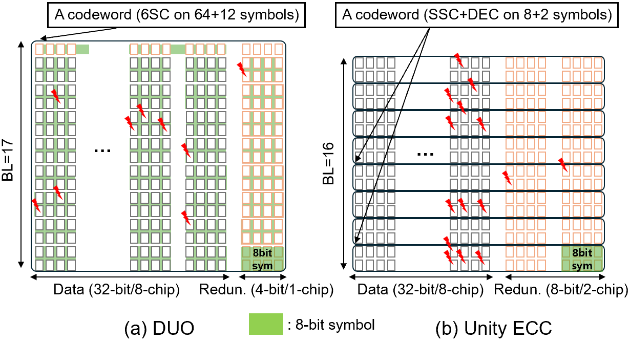
- Bamboo ECC: A symbol-based ECC scheme that groups bits across I/O beats to correct pin-level faults efficiently. "Bamboo ECC forms 8-bit symbols across eight I/O beats, allowing correction of up to four faulty pins ( one chip failure)"
- Bank group: A DRAM internal grouping of banks used to structure access and decoding operations. "decodes every read within each bank group (blue in Fig.~\ref{fig:back})."
- Bank-group decoder: A decoder operating at the bank-group level inside the DRAM to perform on-die corrections. "On reads, a bank-group decoder corrects storage-side faults within the device (O-ECC)"
- BCH codes: Algebraic error-correcting codes capable of correcting multiple bit errors with redundancy that grows roughly with t log n. "More powerful BCH codes correct bit errors in an bit word with redundancy on the order of bits"
- Bounded Fault (BF): A constraint that ensures miscorrections remain within a defined spatial region to avoid amplifying errors across symbols. "To prevent such cross-layer interference, DDR5 enforces the Bounded Fault (BF) rule"
- Burst length: The number of transfer beats per DRAM burst transaction. "DDR5 reshapes S-ECC design by doubling the burst length (from 8 to 16 beats)"
- Chipkill-Correct: A vendor-specific scheme that enables recovery from a failed DRAM chip using RS coding across devices. "AMD’s Chipkill-Correct constructs 8-bit RS symbols by grouping two 4-bit data beats from each chip"
- Correction radius: The maximum error weight or pattern a decoder can correct for a given code. "Detected but Uncorrectable Error (DUE) when lies beyond the correction radius;"
- Cyclic Redundancy Check (CRC): A polynomial-based checksum used for error detection on data transmissions. "DDR5 employs an 8-bit Cyclic Redundancy Check (CRC) per four DQs"
- Data Bus Inversion (DBI): A signaling technique that inverts data to reduce switching activity and power on the bus. "2 bytes carrying either L-ECC redundancy or Data Bus Inversion (DBI) information."
- Data Pin (DQ): An individual data I/O line in the memory interface. "such as a chip or Data Pin (DQ)"
- Detectable and Correctable Error (DCE): An error condition that is both detected and corrected by the ECC decoder. "Decoding outcomes are commonly categorized as: (1) Detectable and Correctable Error (DCE);"
- Detected but Miscorrected Error (DME): A condition where the decoder claims success but outputs an incorrect codeword. "(3) Detected but Miscorrected Error (DME), in which the decoder asserts success yet outputs an incorrect codeword;"
- Detected but Uncorrectable Error (DUE): An error that is detected but cannot be corrected by the ECC. "(2) Detected but Uncorrectable Error (DUE) when lies beyond the correction radius;"
- ECC-DIMM: A memory module that includes additional pins/devices to carry ECC redundancy. "A standard DDR4 ECC-DIMM provides a -bit interface"
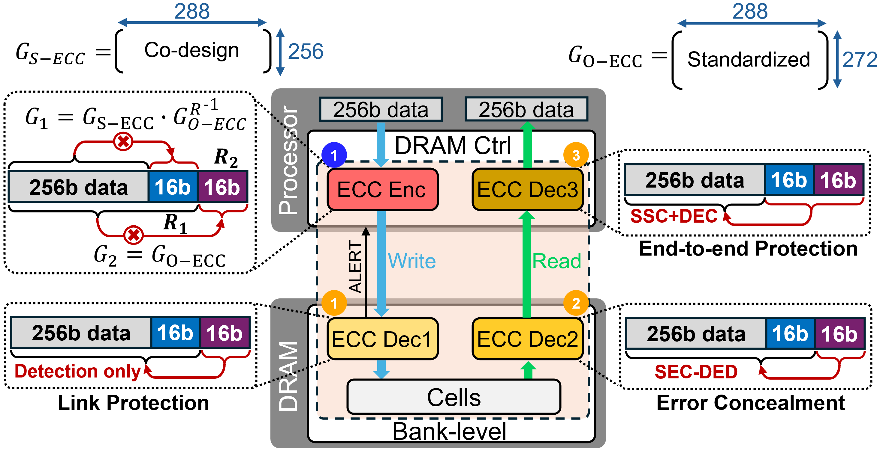
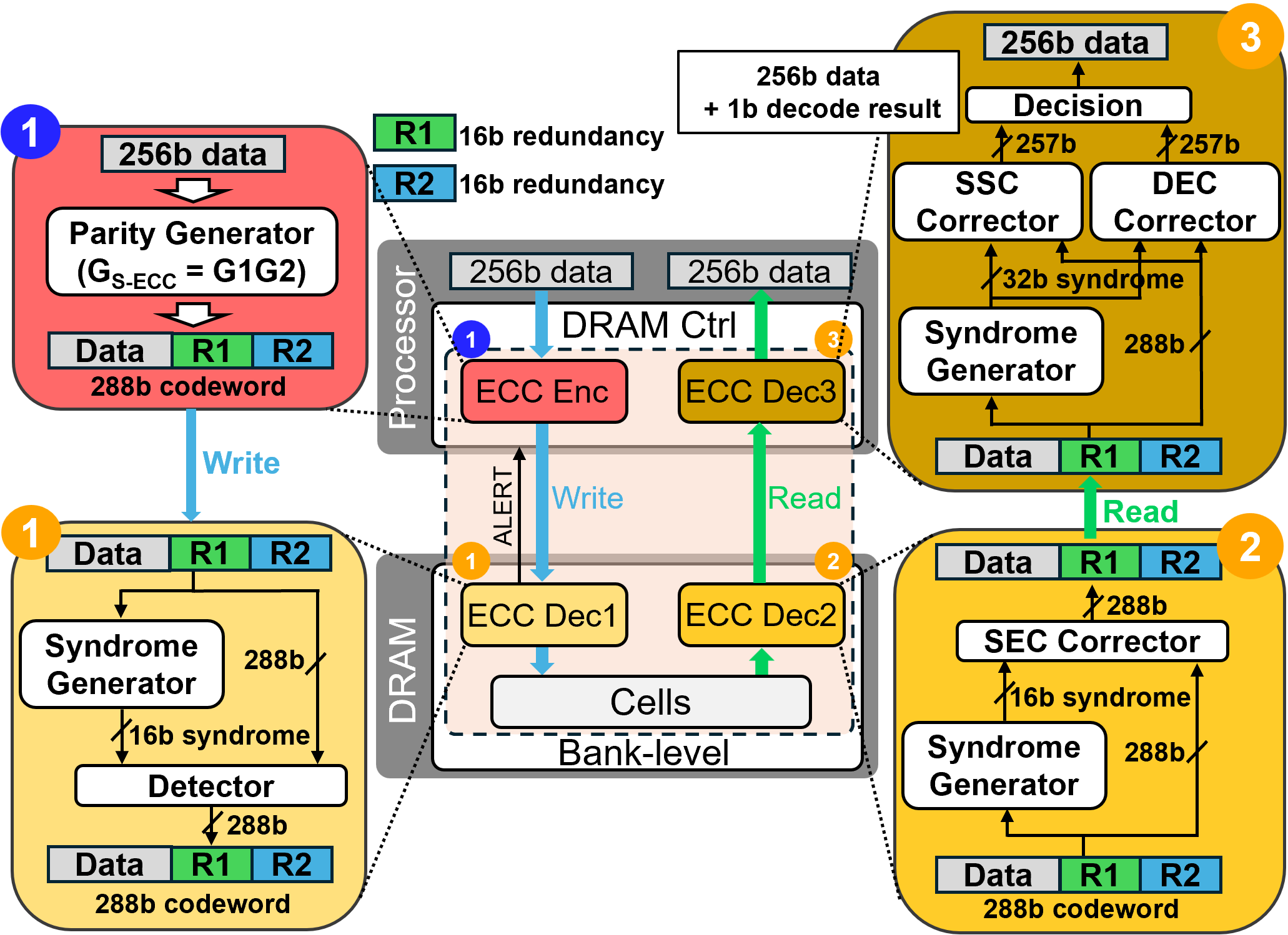
- Encode-Once, Decode-Many (EODM): An architecture where data is encoded once and the redundancy is reused by multiple layers for detection/correction. "At its core is an Encode-Once, Decode-Many (EODM) architecture"
- Error Correcting Codes (ECC): Codes that add redundancy to detect and correct errors in storage or transmission. "Error Correcting Codes (ECC) enable reliable storage and transmission in the presence of physical faults."
- Error Detecting Code (EDC): A code that detects errors but does not necessarily correct them. "This limited budget can be used for either an %error-correcting code ECC (e.g., SEC-DED) or an Error Detecting Code (EDC) (e.g., CRC16)."
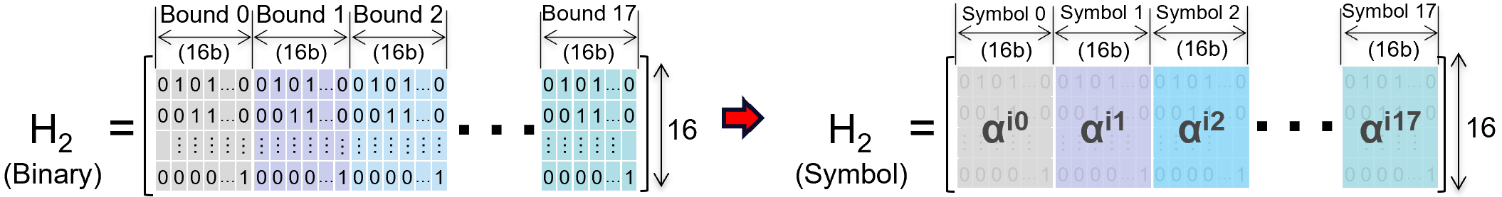
- GF(2m): A finite field of size used for non-binary coding such as Reed–Solomon. "Reed–Solomon (RS) codes defined over can correct up to symbol errors"
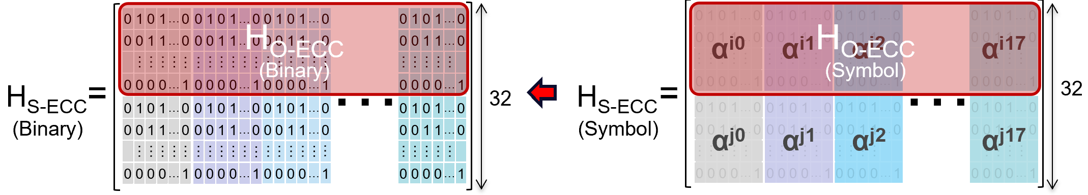
- Generator matrix: A matrix used in linear block codes to map messages to codewords. "A code can be described by a generator matrix with "
- HBM: High Bandwidth Memory, a 3D-stacked memory with wide interfaces and high throughput. "The risk is especially pronounced in recent DRAM families such as HBM and LPDDR."
- HBM4: A specific generation of HBM with defined ECC allocations across layers. "In HBM4, each pseudo-channel protects 32 bytes of data with 2 bytes of S-ECC, 4 bytes of O-ECC, and 1 byte of L-ECC redundancy"
- Link ECC (L-ECC): ECC applied on the memory I/O link for rapid detection (and sometimes correction) of transmission errors. "Link ECC (L-ECC) protects data during transmission between the memory controller and DRAM"
- LPDDR6: The sixth-generation low-power DRAM standard with specific ECC/link protection features. "LPDDR6 adopts 16-bit parity, configurable for either single-error correction or detection-only operation."
- Memory Array Tile (MAT): A DRAM subarray structure that contributes bits per access and shares some peripheral circuits. "each access transfers 8 bits of data from multiple Memory Array Tiles (MATs)."
- On-die ECC (O-ECC): ECC implemented within the DRAM die to repair local faults and improve yield. "Modern DRAMs integrate On-die ECC (O-ECC) to locally repair manufacturing defects and small-scale faults"
- Parity-check matrix: A matrix that defines parity relations and is used to compute the syndrome for decoding. "and a parity-check matrix with ."
- Pseudo-channel: A logical subdivision of an HBM channel used for organizing data transfers and protections. "In HBM4, each pseudo-channel protects 32 bytes of data"
- Rank-level protection: Module-level resilience allowing recovery from a failed device across a memory rank. "traditional multi-device DDR modules can tolerate a failed device through rank-level protection"
- Reed–Solomon (RS) codes: Non-binary symbol-based codes that correct multiple symbol errors using finite-field arithmetic. "Reed–Solomon (RS) codes defined over can correct up to symbol errors"
- Row hammering: A DRAM disturbance phenomenon where repeated activations of a row can induce bit flips in adjacent rows. "disturbance effects such as row hammering"
- Severity (SEV) pin: A DRAM signal pin that reports coarse error severity information from O-ECC to the system. "the results are conveyed to the system level only through a limited severity (SEV) pin"
- Single-Device Data Correction (SDDC): End-to-end ECC capability to recover from a complete device failure. "stronger resilience against complete device failures—known as Single-Device Data Correction (SDDC) or chipkill-correct"
- Single Symbol Correction (SSC): Symbol-level correction that repairs errors confined to a single ECC symbol. "configuring S-ECC as an 8-bit Single Symbol Correction (SSC) allows correction of up to 8-bit clustered errors"
- Single-Error Correction, Double-Error Detection (SEC-DED): A common ECC that corrects one bit error and detects two bit errors per word. "The most common main‑memory code is Single‑Error Correction and Double‑Error Detection (SEC-DED)"
- Single-device-per-channel (SDPC): An organization where a single DRAM device provides the entire channel’s data, common in HBM/LPDDR. "a single-device-per-channel (SDPC) organization"
- Subwordline (SWL): An internal DRAM wordline segment controlling subsets of cells. "such as subwordline (SWL) and subwordline drivers (SWD)"
- Subwordline driver (SWD): A peripheral circuit that drives subwordlines and can induce multi-bit errors when faulty. "such as subwordline drivers (SWD)"
- Syndrome: The vector computed from received data using the parity-check matrix, used to infer error patterns. "the decoder computes the syndrome "
- Through-Silicon Vias (TSVs): Vertical interconnects in stacked memory that introduce distinct fault modes outside O-ECC’s scope. "where Through-Silicon Vias (TSVs) introduce new fault modes."
- Undetectable and Uncorrectable Error (UUE): An error state where the syndrome is zero despite corruption, escaping detection. "and (4) Undetectable and Uncorrectable Error (UUE) with despite corruption"
- Unity ECC: A hybrid ECC that handles both symbol-level and bit-level errors through combined decoding techniques. "More recently, Unity ECC extends this concept to handle both single-symbol and double-bit errors through hybrid decoding"
- Variable Retention Time (VRT): A phenomenon where DRAM cells exhibit fluctuating data retention times due to variation and aging. "more susceptible to charge leakage, variable retention time (VRT), and disturbance effects"
Collections
Sign up for free to add this paper to one or more collections.