- The paper's main contribution is the development of a low-cost inertia dynamometer using project-based learning with vocational students.
- The methodology combines precise CAD modeling, dual-method moment of inertia calibration, and a commodity sensor-based data acquisition system.
- Empirical validation using a 50 cc engine demonstrates the apparatus's capability to accurately reconstruct torque and power curves for educational purposes.
Building a Low-Cost Inertia Dynamometer in Vocational Education: Technical and Pedagogical Insights
Introduction
This paper presents the conception, fabrication, and classroom integration of a low-budget inertia dynamometer, developed as a year-long, project-based learning (PBL) activity with adult students in a Greek Evening Vocational High School (EPAL) (2604.22008). The initiative aimed to demystify rotational dynamics for a traditionally underrepresented and disengaged group, leveraging their tacit mechanical expertise while fostering context-driven, situated learning. The device enables the quantitative assessment of torque and power delivered by small engines—specifically a culturally salient 50 cc moped—via acceleration of a flywheel with known moment of inertia.
Apparatus Design and Fabrication
The central measurement principle is classical: infer torque via τ=Iα by measuring the angular acceleration α of a flywheel with moment of inertia I. The architecture centers on a 38 kg steel drum, precisely machined and dynamically balanced to ensure mechanical integrity at high angular velocities.
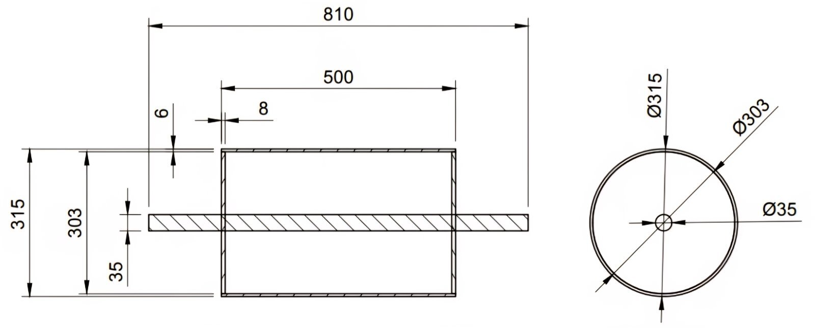
Figure 1: Engineering drawing of the drum and shaft assembly, capturing all dimensional and mechanical details.
Comprehensive CAD modeling underlies both the drum and the entire dynamometer assembly, allowing reproducibility and documentation of technical specifications.
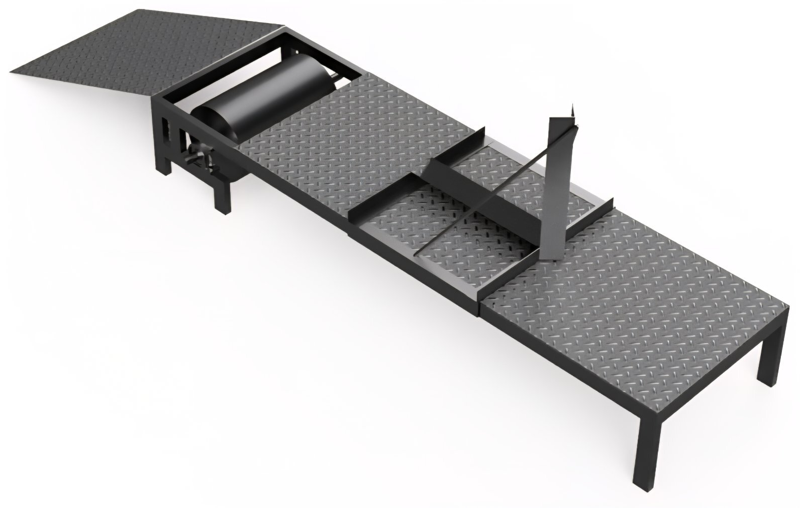
Figure 2: CAD rendering of the completed dynamometer, illustrating all mechanical subsystems.
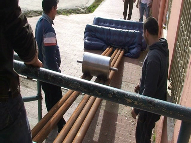
Fabrication was a core pedagogical element. Students executed all arc welding, exploiting their preexisting vocational proficiency and facilitating an inversion of the traditional student-teacher hierarchy.
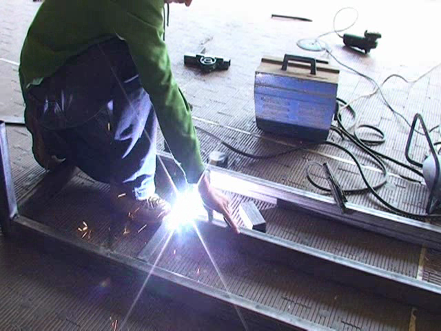
Figure 3: Students performing arc welding on the steel frame in the schoolyard, integrating hands-on fabrication with theoretical instruction.
Critical safety precautions were enforced, given the substantial kinetic energy stored in the drum during operation and the use of Class 2–3R lasers and industrial-grade tools.
Moment of Inertia Calibration
Accurate quantification of I is essential: systematic errors in I propagate linearly into all computed torques and powers. The authors implemented two cross-validating approaches:
A complete free-body model supports this analysis.
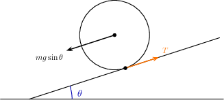
Figure 5: Free-body diagram of the drum on the inclined ramp, with all relevant forces labeled.
The measured result, Iexp=0.651±0.012 kgm2, is in excellent agreement with the geometric calculation, confirming the apparatus's suitability for data-driven torque reconstruction.
Data Acquisition System
The rotational period was digitized by an optical interrupter: a laser beam periodically blocked by a blade attached to the rotating shaft, detected via a cadmium-sulphide (CdS) light-dependent resistor (LDR) connected in a voltage divider. The resulting analog signal was transmitted directly to a laptop’s sound card used as an analog-to-digital converter, sampling at 44.1 kHz.
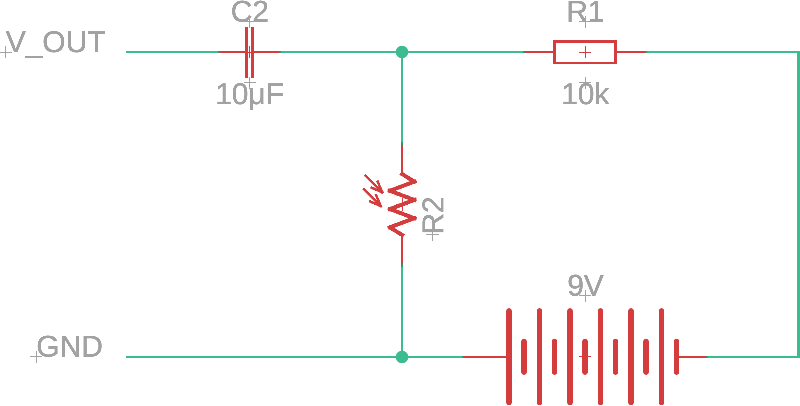
Figure 6: Schematic of the optical-interrupter and front-end electronics, including LDR and decoupling circuit.
A block diagram contextualizes the end-to-end measurement chain.
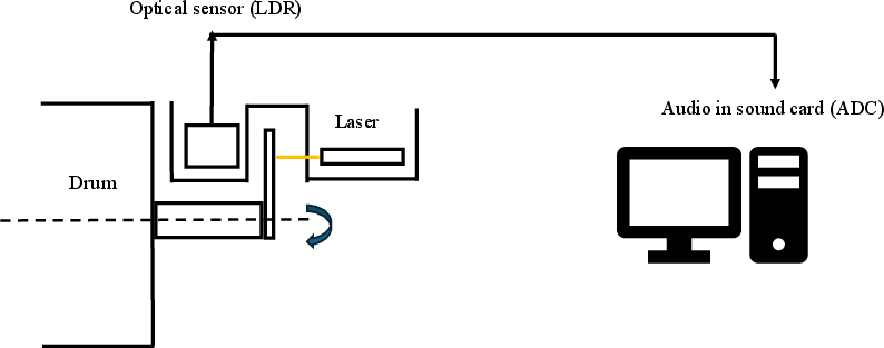
Figure 7: System diagram charting all signal pathways from mechanical interruption through electronics to digital capture.
This DAQ chain, relying exclusively on commodity and surplus hardware, enables sub-millisecond timestamp resolution at essentially no cost.
Signal Processing Pipeline
The raw acoustic data undergo sophisticated digital signal processing:
- Denoising and Pulse Detection: Zero-crossings and local maxima determination following moving-average filtering.
- Angular Velocity Extraction: Finite differencing of pulse timestamps; midpoints assigned for ω values.
- Acceleration Estimation: Instead of noisy direct differences, a low-order polynomial fit (3rd order found optimal) to angular velocity versus time provides a physically smooth α(t).
- Torque/Power Computation: Direct assertion of α0 and α1 at every data point.
Empirical Validation and Results
Testing used a modified 50 cc scooter equipped with a continuously variable transmission (CVT), chosen for its local cultural relevance and pedagogical value. The apparatus performance was validated by running wide-open-throttle (WOT) acceleration sweeps.
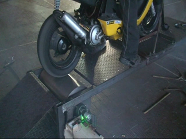
Figure 8: Completed dynamometer under test, interfacing with the Piaggio NRG scooter during a WOT run.
Raw data traces display clear pulse intervals until sensor bandwidth limits emerge.
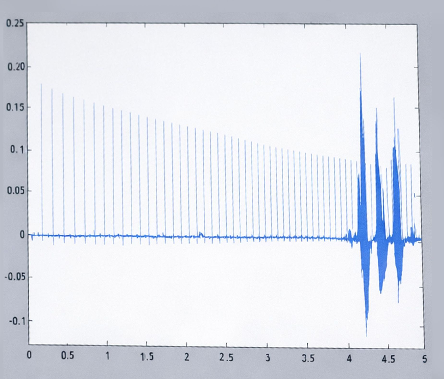
Figure 9: Example segment of raw pulse data; amplitude attenuation at high speeds is caused by LDR recovery time constraints.
The reconstructed torque and power curves reveal the expected plateau in mechanical power and declining torque as angular velocity increases, mirroring the theoretical signature of a CVT holding engine RPM at its peak-power regime.
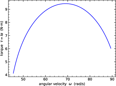
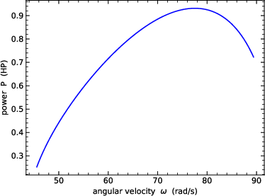
Figure 10: Top—Torque vs. angular velocity curve; Bottom—Power vs. angular velocity. Both shapes reflect correct dynamometer operation and physical CVT characteristics.
A pedagogically rich hardware failure emerged: at high rotations-per-minute, the LDR’s recovery time (α2–α3 ms) became rate-limiting, blurring the pulse train and limiting usable data to subcritical RPMs. This failure, reframed as an opportunity for productive failure, led students to investigate photoconductive physics, analyze timescales, and propose advanced sensor substitutions (photodiode, Hall sensor) and microcontroller-based DAQ solutions.
Pedagogical and Theoretical Implications
The PBL approach anchored abstract rotational dynamics in real-world fabrication and measurement tasks. By integrating student expertise and promoting agency during construction and troubleshooting phases, the project fostered self-efficacy and community learning. While traditional assessment tools (pre/post conceptual inventories) were not deployed, participant engagement and qualitative learning outcomes were notable; however, the lack of formal educational evaluation is a recognized limitation.
From a technical standpoint, the work demonstrates that FA-grade dynamometer principles and torque/power curve reconstruction are achievable without commercial data acquisition hardware or high-end sensors, provided careful calibration and error-checking are implemented.
Future Directions
Potential improvements include:
- Upgrading the sensing hardware for higher RPM measurement (e.g., solid-state photodiodes, Hall sensors).
- Implementing microcontroller-based DAQ for direct digital pulse capture.
- Calibration against commercial reference instruments.
- Systematic assessment of physics learning outcomes in future replications.
Conclusion
This study documents a cost-minimal, technically sound inertia dynamometer co-constructed with vocational students, serving both as a practical instrument and a vehicle for authentic physics engagement. The apparatus delivers reliable qualitative torque and power characterization in small-engine contexts, and the project serves as a transferable framework for integrating PBL approaches in under-resourced educational settings.