- The paper introduces impedance-based indices (OII, CFI, VFI) to quantitatively classify grid-forming converter behavior in DC microgrids.
- It develops a small-signal framework that integrates device and control dynamics, enabling frequency-domain analysis of controller performance.
- Experimental and simulation results validate that controllers with sub-unity indices enhance voltage stability and minimize transient deviations.
Introduction
The paper "Grid-Forming Characterization in DC Microgrids" (2604.12804) establishes a rigorous analytical approach for evaluating and categorizing the behavior of source converters within DC microgrids. Despite DC microgrids' proliferation fueled by integration with renewable energy and the efficiency of power electronic converters, a central theoretical gap persists: the lack of device-level metrics that can systematically define and quantify "grid-forming" actions, analogous to those well-appreciated in AC systems. This work addresses the ambiguity inherent in the application of AC concepts (e.g., grid-forming versus grid-following) to DC contexts by introducing three impedance-based quantitative indices, enabling unambiguous classification of converter behavior with direct implications for decentralized control design and microgrid voltage stability.
System Modeling and Control Architectures
The analysis centers on a canonical system—a bidirectional boost DC/DC converter interfaced to a DC microgrid (Figure 1). The control hierarchy consists of a fast inner current PI loop and diverse decentralized outer-loop strategies, including I-V and V-I droop control, and the Virtual DC Machine (VDCM) scheme.
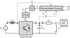
Figure 1: Source DC/DC (bidirectional boost) converter connected to a DC microgrid with the associated control blocks shown.
A small-signal framework is formalized, allowing analytical derivation of closed-loop output impedance. The converter and its control structure are linearized and abstracted as a controlled voltage source in series with frequency-dependent impedance, with explicit modeling of the output capacitance. This enables precise mapping from disturbances (either current or grid-side voltage) to terminal voltage excursions—critical for control performance and stability assessment.
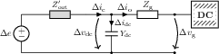
Figure 2: Small-signal equivalent circuit of the source converter integrating both device and control dynamics.
Output Impedance-Based Indices
The core contribution is the formulation of three indices:
- Output Impedance Index (OII): Quantifies the degree to which the converter can suppress output current disturbances in terms of terminal voltage, normalized by the control droop gain.
- Current-Forming Index (CFI): Characterizes how the converter’s current responds to output current disturbances, capturing current-source (current-following), current-forming, or disturbance-amplifying behavior.
- Voltage-Forming Index (VFI): Measures the converter’s sensitivity to grid/PCC voltage disturbances; a critical indicator of voltage-source behavior in parallel-converter, low-inertia DC grids.
Each index yields a precise dichotomy: values below (or equal to) unity correspond to "voltage-forming" or "current-forming" operation, while values above unity indicate disturbance amplification—potentially destabilizing or leading to unsatisfactory transient performance.
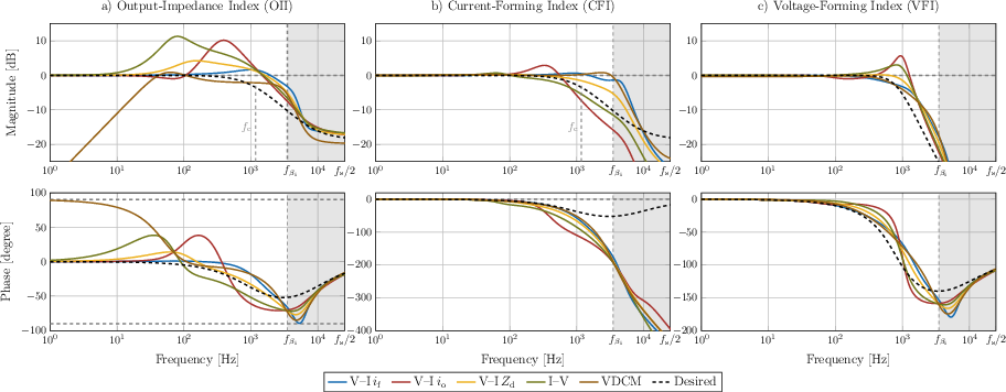
Figure 3: Frequency-domain plots of OII (a), CFI (b), and VFI (c) for diverse boost converter control architectures, indicating operational regimes and bandwidth-limited behavior.
Control Algorithm Comparison and Results
Frequency-domain analysis using these indices reveals that conventional control algorithms span a continuum of behaviors:
- V-I with filter current feedback and VDCM effectively approximate the desired grid-forming impedance across relevant frequencies, ensuring bounded voltage deviations under load changes and attenuating high-frequency disturbances.
- I-V droop and other V-I variants tend to enter disturbance-amplifying regimes in moderate to high frequencies, evidenced by OII and CFI overshoot beyond unity.
This theoretical classification is substantiated by time-domain simulations in a DC microgrid benchmark including constant power loads (Figure 4). Controllers with sub-unity OII demonstrate minimal DC bus voltage undershoot following a load step, closely tracking the response of an ideal voltage source (as predicted by the desired impedance synthesis).
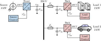
Figure 4: Schematic of a DC microgrid containing a source converter and two constant power loads.
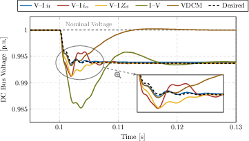
Figure 5: Time-domain trajectories of DC bus voltage following a load increase, illustrating correspondence between analytical index-based predictions and practical transient voltage performance.
Theoretical and Practical Implications
The analytical framework enables device-level characterization that is independent of system context, facilitating the design and tuning of converter controllers for robust grid-forming behavior. The indices are grounded in physical measurements—output impedance and capacitance—directly linking passivity-based stability criteria with practical control parameters (e.g., droop gain, bandwidth).
Key insights include:
- Quantitative boundary for grid-forming: Converters are guaranteed to remain in the grid-forming region (per OII ≤ 1) up to a calculable crossover frequency defined by output capacitance and droop gain, guiding optimal component and controller sizing.
- Unified evaluation: Indices provide a frequency-resolved tool for direct comparison across disparate algorithms, obviating the need for comprehensive time-domain simulation for every control design iteration.
These properties generalize beyond the specific microgrid case: they could underpin standardized device specifications, support plug-and-play interoperability in multi-vendor systems, and inform the development of new impedance-shaping controls with guaranteed stability margins.
Future Directions
The paper's device-level impedance indices suggest broader application. Extension to multi-converter networks, including systems with nonlinear or time-varying loads, will further validate these metrics as universal indicators for converter-in-the-loop stability and performance. Moreover, exploring the relationship between the indices and system-level phenomena such as bus stiffness, secondary control, and fault ride-through may yield scalable, modular approaches for large-scale DC grids.
Conclusion
"Grid-Forming Characterization in DC Microgrids" (2604.12804) systematically addresses a foundational gap in DC microgrid analysis by introducing impedance-based, frequency-resolved indices for converter forming behavior. These metrics provide rigorous, physically grounded standards for evaluating and tuning converter controls, with demonstrated predictive power in both frequency- and time-domain performance. The framework sets the stage for robust, analytically guided grid-forming controller design and fosters a deeper quantitative understanding of DC microgrid dynamics.

