- The paper demonstrates that optimized electrode geometries enable a Cavallo multiplier to achieve a gain of 18 with peak fields controlled to 116 kV/cm.
- It leverages parametric sweeps and finite element analyses to minimize breakdown probability in pressurized liquid helium at 1520 Torr.
- The design incorporates spark localization via sacrificial 'spark buttons', ensuring robust performance for generating 650 kV in cryogenic nEDM experiments.
Electrode Optimization for Cryogenic Cavallo Multipliers in nEDM Experiments
Introduction
The Cavallo multiplier, an electrostatic induction device, is highly suited for generating electrically isolated, low-noise high voltages, particularly in environments where classical high-voltage feedthrough implementation is impractical. This is specifically the case for cryogenic precision experiments, such as the neutron electric dipole moment (nEDM) measurement in liquid helium at sub-kelvin temperatures, which demand both nonmagnetic compatibility and minimal thermal load. The paper "Electrode Design for a Cavallo High Voltage Multiplier in a Cryogenic nEDM Experiment" (2604.10313) provides a comprehensive methodology for optimizing electrode geometries via parametric profile sweeps and finite element analyses (FEA) to simultaneously maximize voltage gain and minimize the probability of electrical breakdown in pressurized liquid helium.
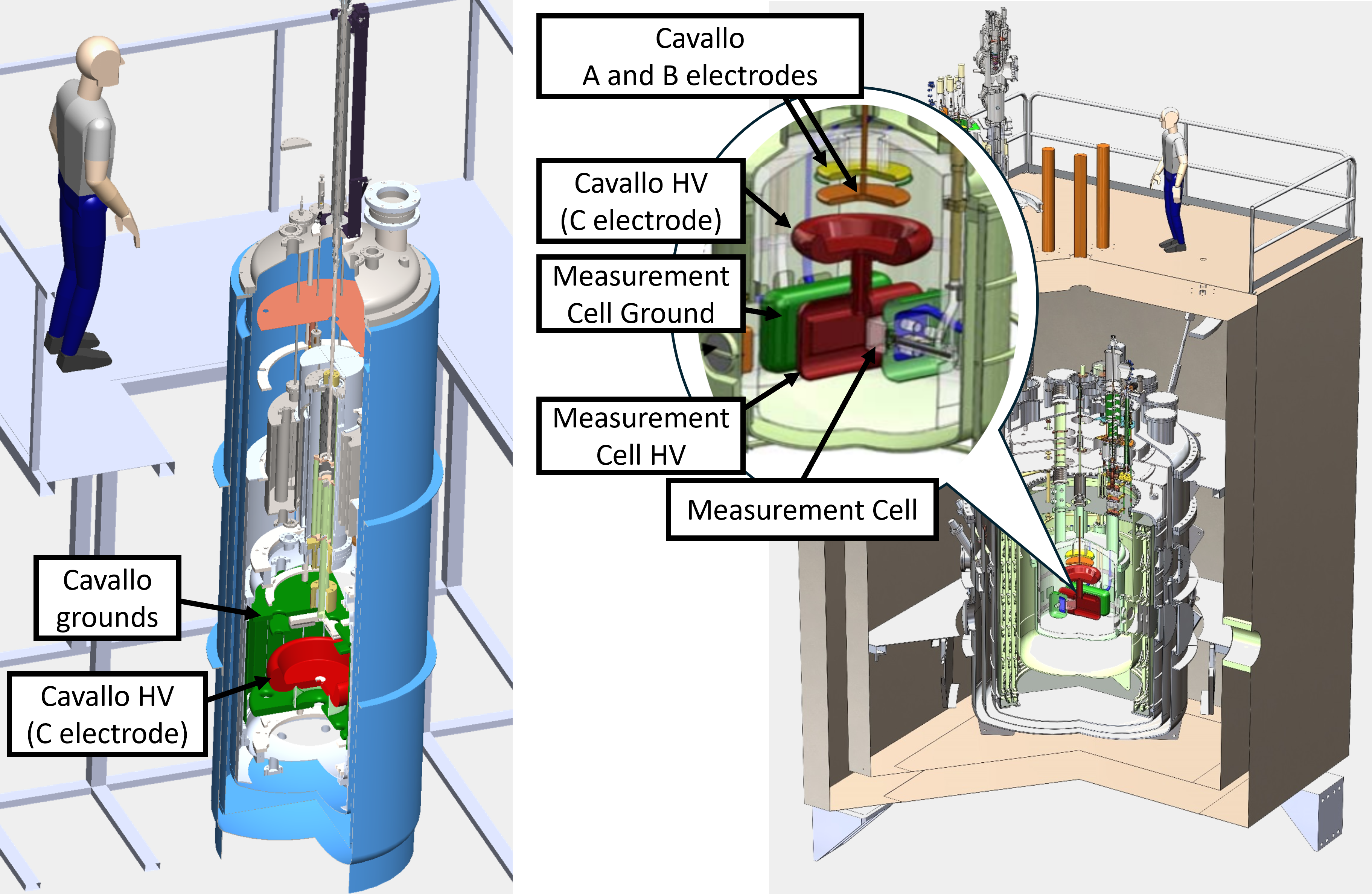
Figure 1: The Cavallo multiplier setup, with detailed placements in both the cryogenic test stand and the nEDM experiment, highlighting the integration of the high-voltage C electrode.
Cavallo Multiplier Principles and Geometric Constraints
The operational principle of a Cavallo multiplier necessitates a mechanically actuated charge transfer between electrodes A (input), B (shuttle), and C (output), while minimizing direct electrical connection between input and output. A critical parameter is the theoretical gain, determined by the mutual capacitances at key electrode positions. The relevance for nEDM is clear: substantial output voltages (∼650 kV) are required on the measurement-cell electrodes, while input voltages are limited to ∼50 kV due to available feedthrough technology. This sets a target gain near 13–18.
The electrodes must be housed within the inner cryostat volumes to avoid external thermal and electrical coupling. This constraint, along with the requirement for nonmagnetic and cryogenically robust electrode and support materials, restricts allowable geometries and mandates careful electric field management to avoid breakdown.
Electrode Shape Parameterization and Finite Element Simulation
The design strategy leverages parameterized profiles—specifically, hyperbolic-tangent-augmented elliptical segments—for shaping electrodes. This allows high degrees of freedom in tuning local curvature and helps in diffusing peak field regions. FEA using COMSOL provided quantitative predictions of both the electrostatics and surface field distributions. Notably, the C electrode combines a pronounced "lobe" to optimize the CC/CB and QC/QB ratios, increasing theoretical gain while suppressing field enhancement at sensitive edges.
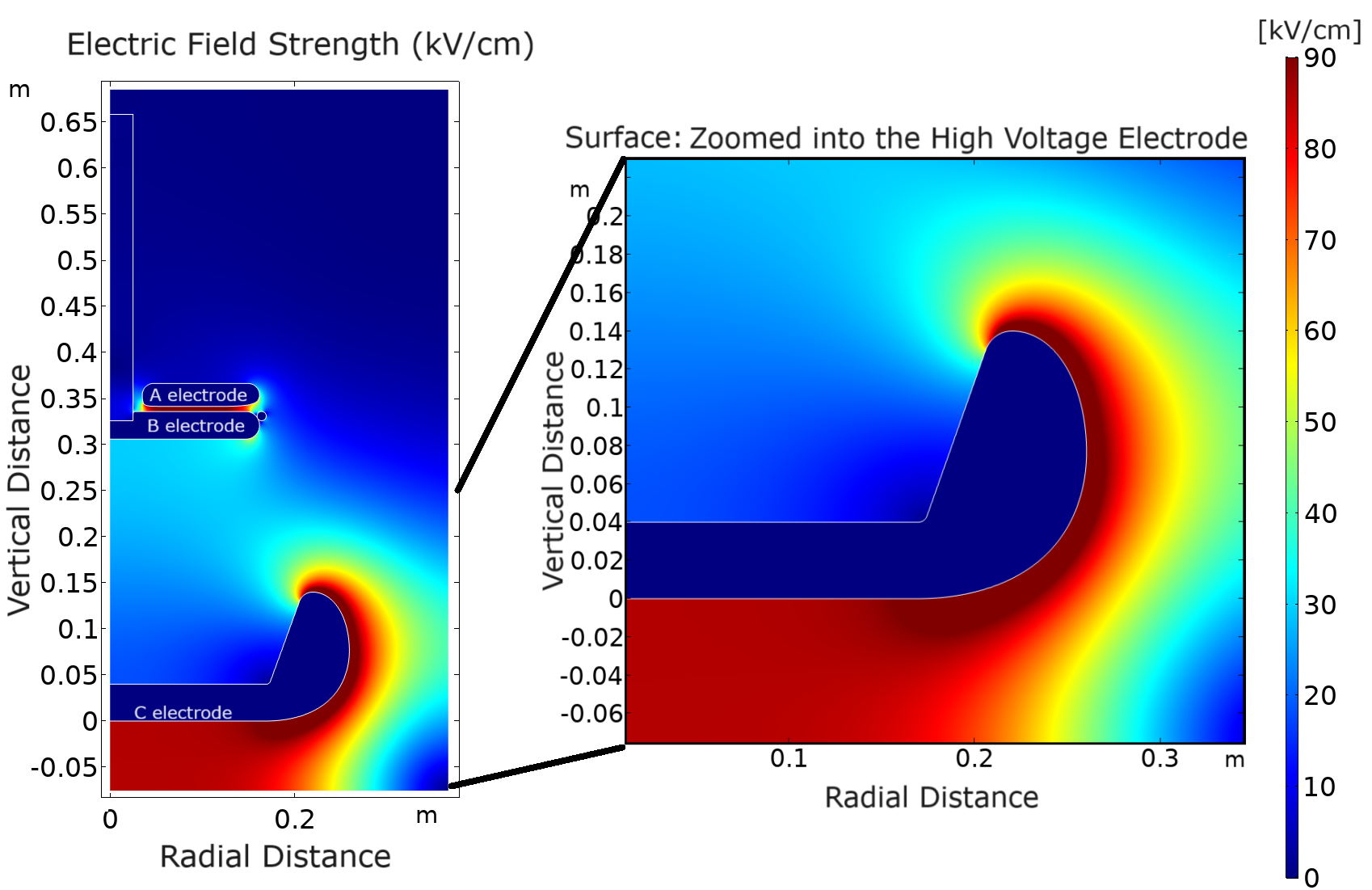
Figure 2: Axisymmetric FEA model showing the refined C electrode with its large lobe, designed for optimal gain and minimized peak electric field.
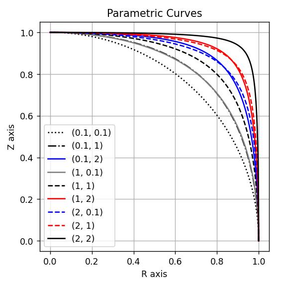
Figure 3: Example parametric electrode profile curves, demonstrating the impact of kr and kz parameters on curvature and field management.
The A and B electrodes present special challenges: the proximity-induced charge loading between A and B requires aggressive edge curvature management to prevent local breakdown during the shuttle's movement. The B electrode, which mechanically traverses both high-field regions near A and C, is given a constant-radius fillet for edge rounding—demonstrated to significantly reduce maximal surface fields compared with simpler fillet geometries.
Detailed Engineering and Breakdown Probability Analysis
Three-dimensional modeling, including hardware features such as mounting and slatted ground returns, confirmed that engineered variations (e.g., PMMA support grooves, access holes) did not compromise the meticulously tuned field distributions.
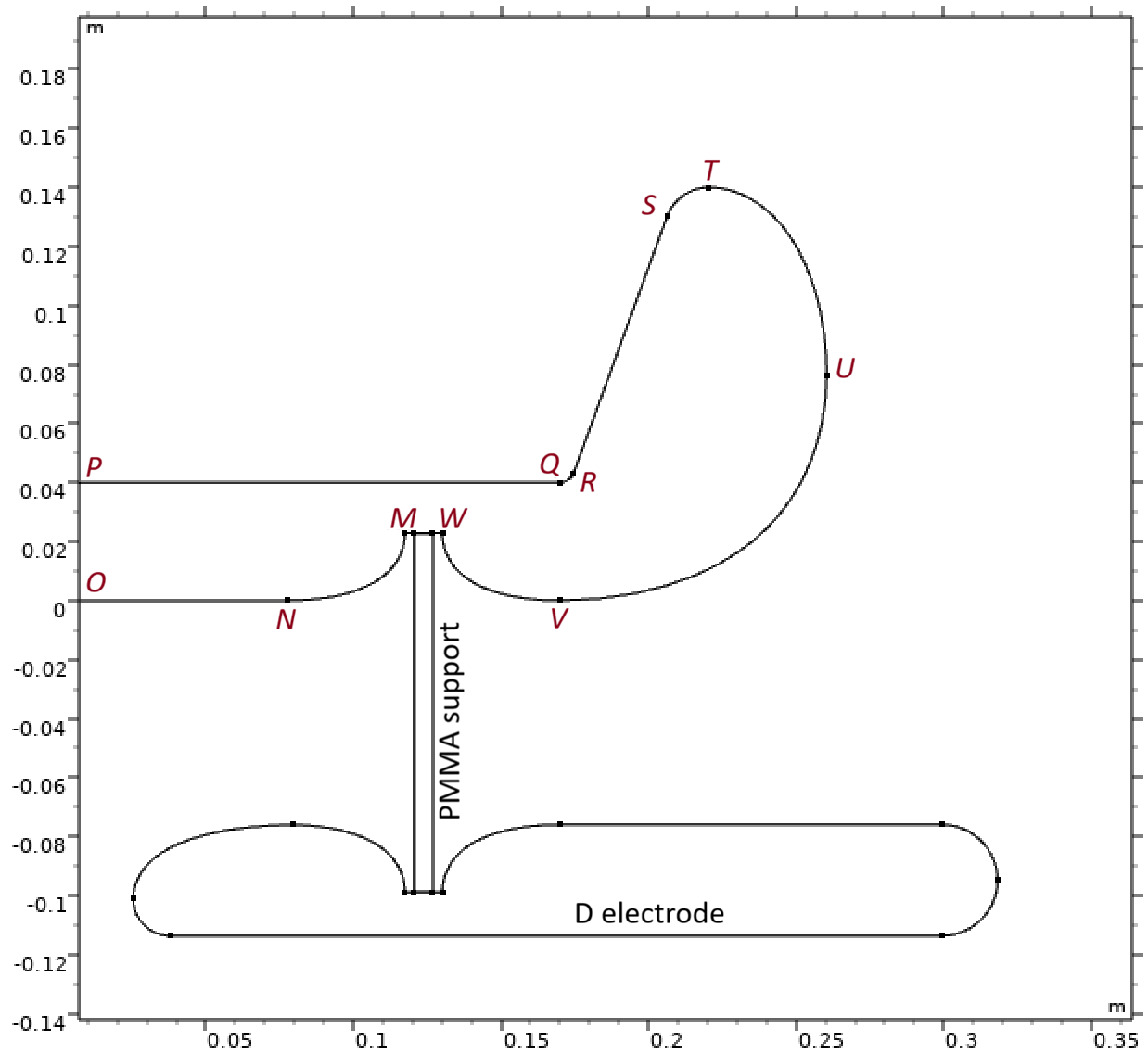
Figure 4: C electrode cross-section with PMMA supports and D electrode for leakage current measurement, with curves and support grooves engineered for field minimization.
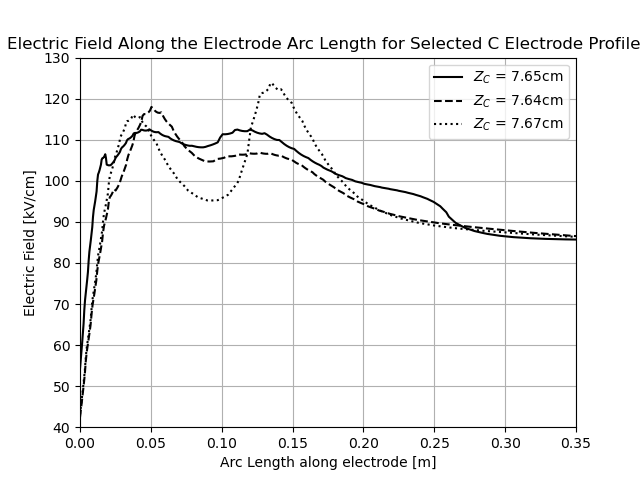
Figure 5: Surface electric field profile along the arc of the C electrode at 650 kV, showing minimized field peaks for the optimized zC configuration.
An advanced statistical breakdown model, following Phan et al.’s formalism, was utilized: the probability of breakdown is a function of the integrated surface area exposed to various field bins rather than a simple field-threshold criterion. This accounts for stochastic initiation mechanisms in LHe and incorporates knowledge of material-specific hazard functions.
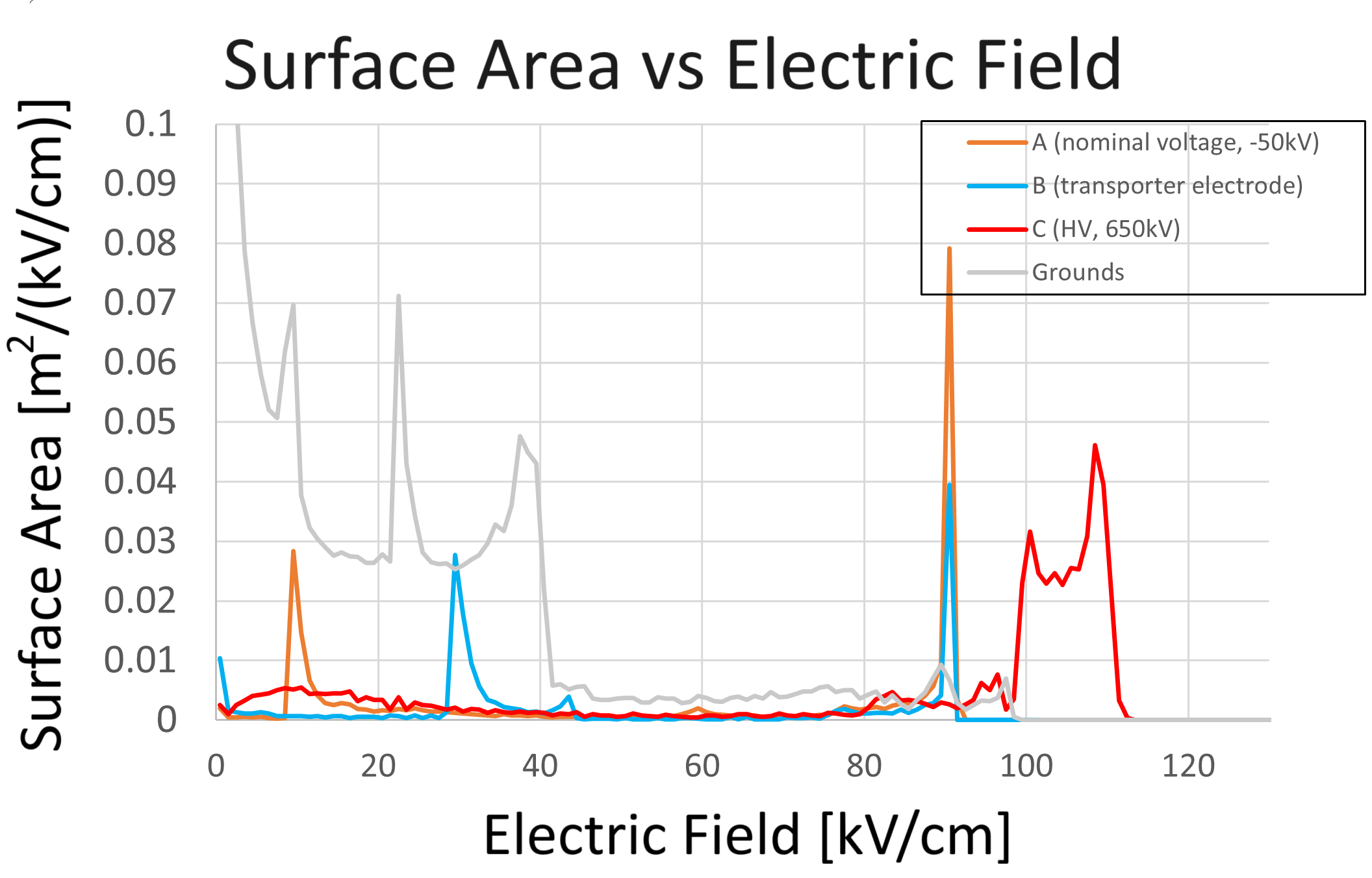
Figure 6: Histogram of electrode surface areas as a function of electric field strength, providing critical input to breakdown probability calculations.
Calculated breakdown probabilities show that, for the final geometry operating at the experimental design pressure (1520 Torr), the risk of breakdown at 650 kV is negligible (≤10−6). Notably, the breakdown risk for the Cavallo electrodes remains below that of the actual measurement cell electrodes, supporting the design's suitability.
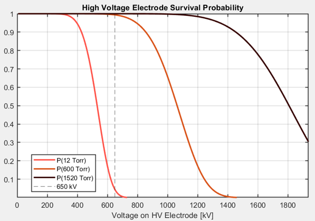
Figure 7: Survival probability of high-voltage electrodes as a function of ramped voltage, illustrating robust breakdown immunity at target operating conditions.
Spark Localization and Operational Considerations
Real-world imperfections make sparking at the B–C interface inevitable during charge transfer. This is addressed by using sacrificial, thickened, replaceable "spark buttons," concentrating the discharge energy in a controlled, low-damage region. FEA simulations show that spark energies can be limited to approximately 10 mJ at sub-millimeter separations, drastically reducing electrode erosion and contamination.
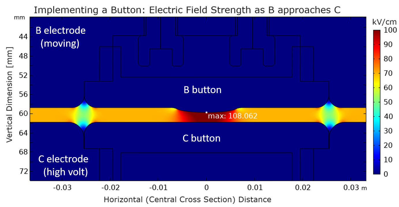
Figure 8: Thickened, replaceable spark buttons at the B and C electrodes, engineered to force sparking at a sacrificial location.
Implications and Outlook
This electrode design, validated through both 2D and 3D FEA alongside probabilistic breakdown modeling, provides a blueprint for robust, high-gain, cryogenically compatible voltage multipliers specifically tailored to the constraints of modern precision experiments. The methodology—comprehensive parametric curve sweeps, area-field distribution analysis, and hazard-function-informed breakdown predictions—establishes a rigorous framework for similar high-voltage applications in cryogenic or ultra-pure dielectric environments.
Practically, such advances directly enable the next generation of nEDM and other low-background measurements, where remote high-voltage generation and minimal electromagnetic interference are crucial. Theoretically, this work exemplifies the interplay between geometric optimization, field engineering, and stochastic breakdown modeling, and will inform future developments in in-situ high-voltage supply systems.
Conclusion
The paper rigorously demonstrates that customized electrode shape optimization, informed by detailed electrostatic simulation and probabilistic breakdown modeling, enables a Cavallo multiplier design capable of delivering 650 kV in liquid helium in fewer than 20 cycles, with a final geometry achieving a gain of 18 and peak fields well-controlled at 116 kV/cm. The results indicate a breakdown probability at least an order of magnitude lower than competing risk surfaces, and spark localization strategies further protect critical surfaces. This design paves the way for robust, low-noise high-voltage production necessary for the next generation of precision cryogenic experiments.
(2604.10313)