- The paper demonstrates that incorporating curved sensors in the WST IFS design simplifies optics and reduces costs by eliminating redundant lenses.
- It employs a two-stage field splitting and image slicer architecture to manage 192 sub-fields, achieving superior image quality over conventional systems.
- Simulation and analytical methods reveal that cylindrical sensors incur only a ~20% spot-size increase, validating their practical use in advanced spectrographs.
Introduction and Motivation
The Wide-field Spectroscopic Telescope (WST) is a proposed 12-meter class facility dedicated to large-scale spectroscopy for next-generation surveys. The unprecedented étendue and broad wavelength range of the WST integral field spectrograph (IFS) establish new requirements on optical and mechanical architecture. The paper “IFS spectrograph designs for the Wide-field Spectroscopic Telescope: Architecture and performance gains from curved sensors” (2604.09488) establishes a comprehensive optical and system-level framework for the WST IFS, focusing on a baseline with flat detectors and subsequent studies leveraging recent advances in curved detector technology. The work rigorously analyzes the impact of detector curvature on spectrograph architecture, image quality, and system cost, culminating in a performance/risk tradeoff between flat, cylindrical, and toroidal sensor designs.
WST IFS Architecture
The WST IFS is optimized for a 3×3 arcmin2 field—nine times larger than MUSE, with an effective collecting area twice as large. The scale of the required multiplexing necessitates a hierarchical field splitting and relay architecture Figure 1, implemented through two successive splitting stages, followed by image slicers and dual-arm spectrographs Figure 2.
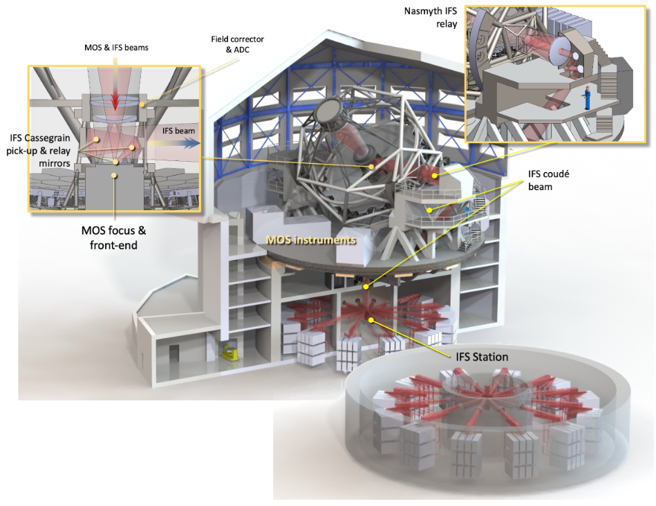
Figure 1: Preview of the WST facility showing the spatial allocation for the IFS system.
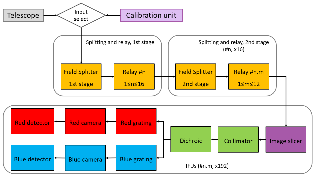
Figure 2: Overall system architecture, including field splitting subsystems feeding the IFUs and double-arm spectrographs.
Field Splitting and Image Slicer Design
The field is initially divided by a 16-element mirror array (first splitting stage) and subsequently by 12-element assemblies in each branch (second splitting stage), producing 192 sub-fields. Each sub-field is then re-formatted by an image slicer so that the 2D sky field is sequentially rearranged into a set of parallel slitlets, forming a long pseudo-slit per spectrograph Figure 3.

Figure 3: The two-stage field splitting, culminating in a grid of sub-fields, each feeding a dedicated image slicer.
Mechanically, the subdivision into two relay stages avoids severe packing constraints and simplifies both as-built analysis and integration relative to monolithic approaches (Figure 4 and 5).
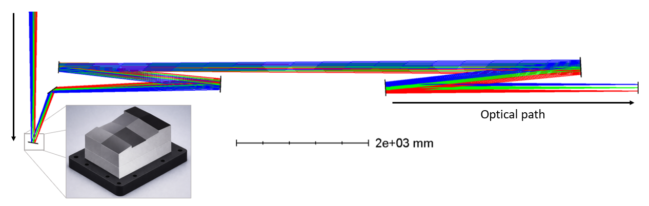
Figure 4: Mirror-based first field splitting concept (detailed with 8-mirror illustration).
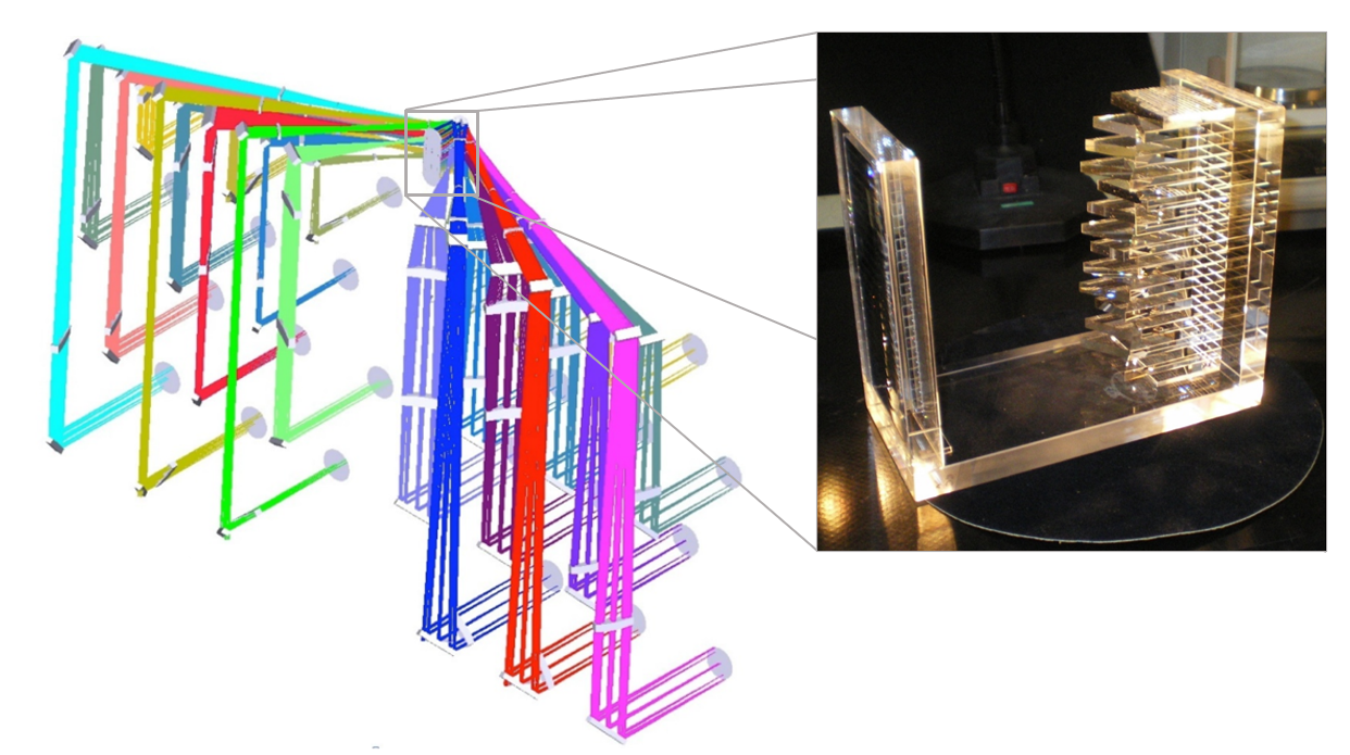
Figure 5: Layout inspired by the MUSE relay stage, adopted with necessary scaling for WST.
The image slicer design uses three reflective elements and two physically separated stacks to control output slit curvature, limit incidence angles, and minimize induced astigmatism Figure 6, representing an evolution over prior two-mirror designs such as those used in MUSE.
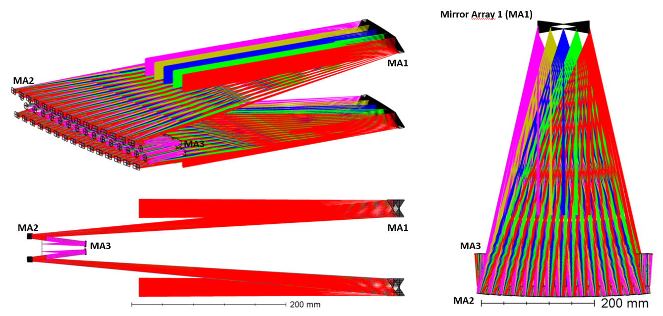
Figure 6: Three-mirror image slicer preliminary design to accommodate WST’s field and output geometry.
Spectrograph Design With Flat and Curved Sensors
Flat Detector Baseline
The baseline spectrograph employs a dual-arm layout (blue: 370–595 nm; red: 575–930 nm) with a compact, all-reflective collimator (two-mirror system), dichroic splitting, and six-element camera per arm Figure 7.

Figure 7: Optical layout with flat detectors, aspheric refractors, and a dichroic splitter separating blue/red arms.
Through careful selection of glasses and coatings, the design achieves high throughput (≥86% in both arms excluding grating, detector quantum efficiency, and dichroic losses), while the image quality, as measured by median FWHM spot sizes, vastly surpasses MUSE—about 0.048" (blue) and 0.046" (red) versus 0.092" for MUSE Figure 8.
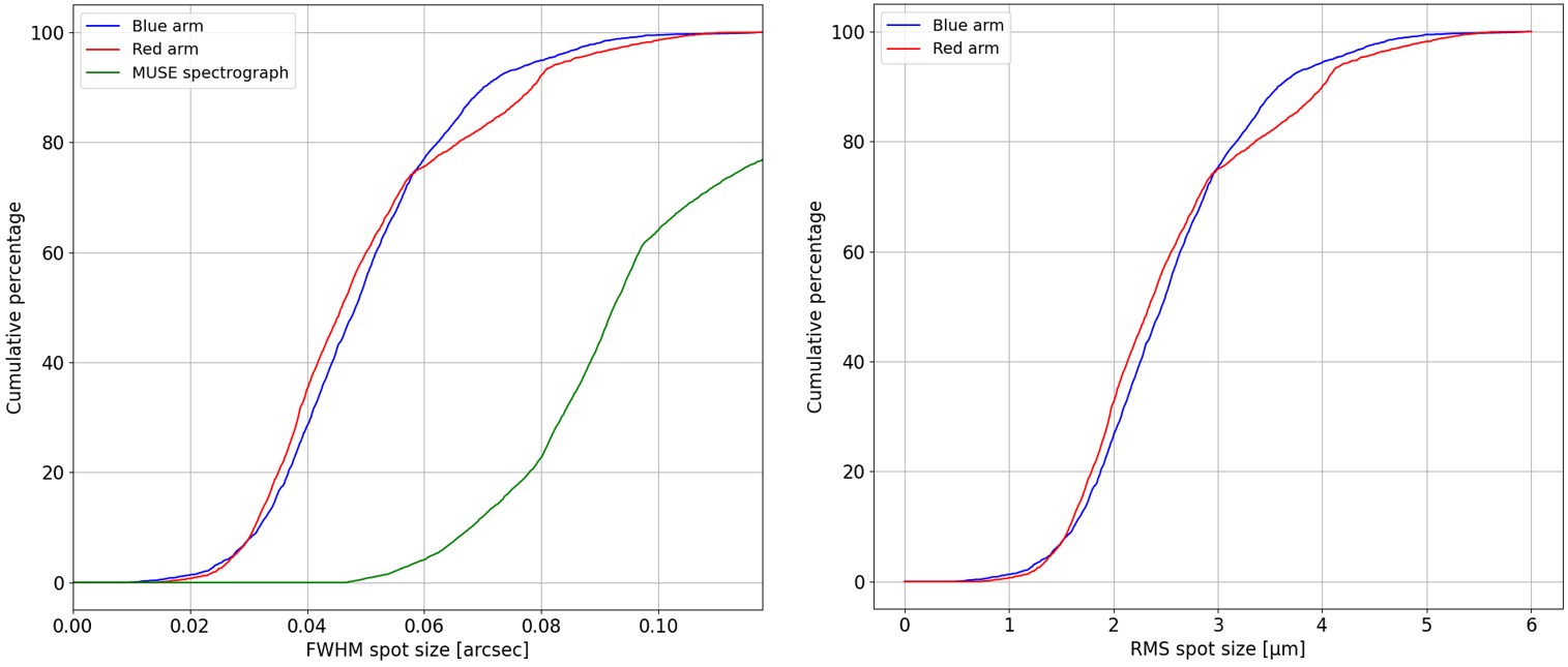
Figure 8: Cumulative FWHM spot size distribution for blue and red arms, flat detector baseline.
Curved Detector Theory and Impact
The theory section establishes that the optimal focal surface for a spectrograph is a tilted toroid, owing to the distinct physical contributions along the spatial and spectral axes: camera and collimator Petzval field curvature, axial chromatism, and the nonlinear mapping inherent to grating dispersion. An explicit formalism is given (Eq. 9 in the manuscript), quantifying the sag of the image surface as a function of wavelength, field position, and system parameters.
Notably, four main contributions to the focal surface are identified:
- Spatial curvature (x2): Sum of camera and collimator field curvature.
- Spectral curvature (y2): Modulated by camera Petzval, axial chromatism, and grating nonlinearity.
- Global tilt (y): Arising from off-axis use and linear chromatism.
- Defocus offset (constant): From off-axis terms, correctable by systematic detector shifts.
The paper demonstrates that the ideal image surface deviates substantially from a plane, motivating the adoption of curved sensors to relax camera complexity, reduce element count, and improve as-built optical quality.
Designs With Curved Sensors
Allowing the detector to be toroidal during optimization yields two possible configurations: a toroidal detector with a flat slit, or a cylindrical detector with a concave slit. The latter, though a slight compromise on image quality, is favored due to vastly reduced fabrication risk and proven manufacturability.
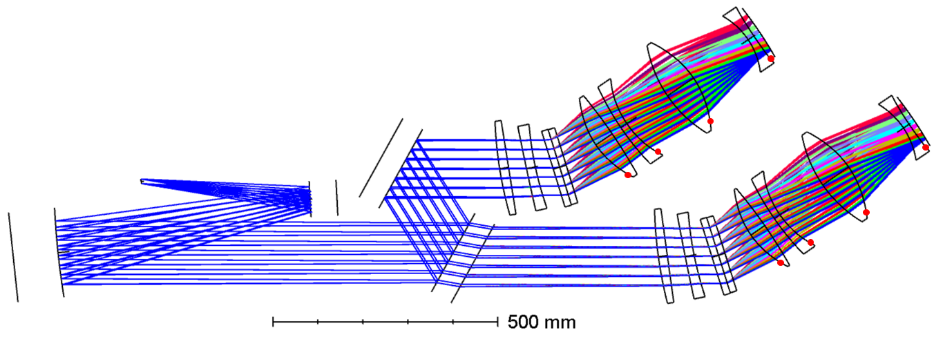
Figure 9: Optical layout with toroidally curved detector showing aspherics and elimination of redundant refractive elements.
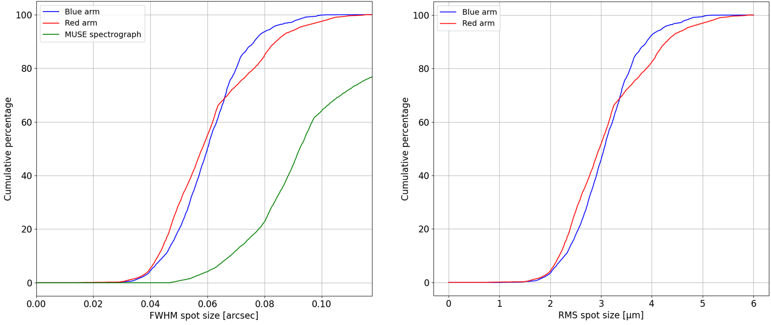
Figure 10: Cumulative FWHM spot size for the cylindrical detector option—median performance ∼0.060" (blue), 0.058" (red).
The curved sensor approach allows removal of two lenses per camera arm (a total of 768 lenses at full scale), yielding not only cost and assembly advantages but a reduction in overall system absorption and scattered light. Theoretical analysis coupled to numerical validation proves that the toroidal and cylindrical detector shapes closely approximate the actual image surface produced by the spectrograph’s aberrations, with residuals dominated by higher-order (e.g., y3–y6) terms (Figures 11 and 12).
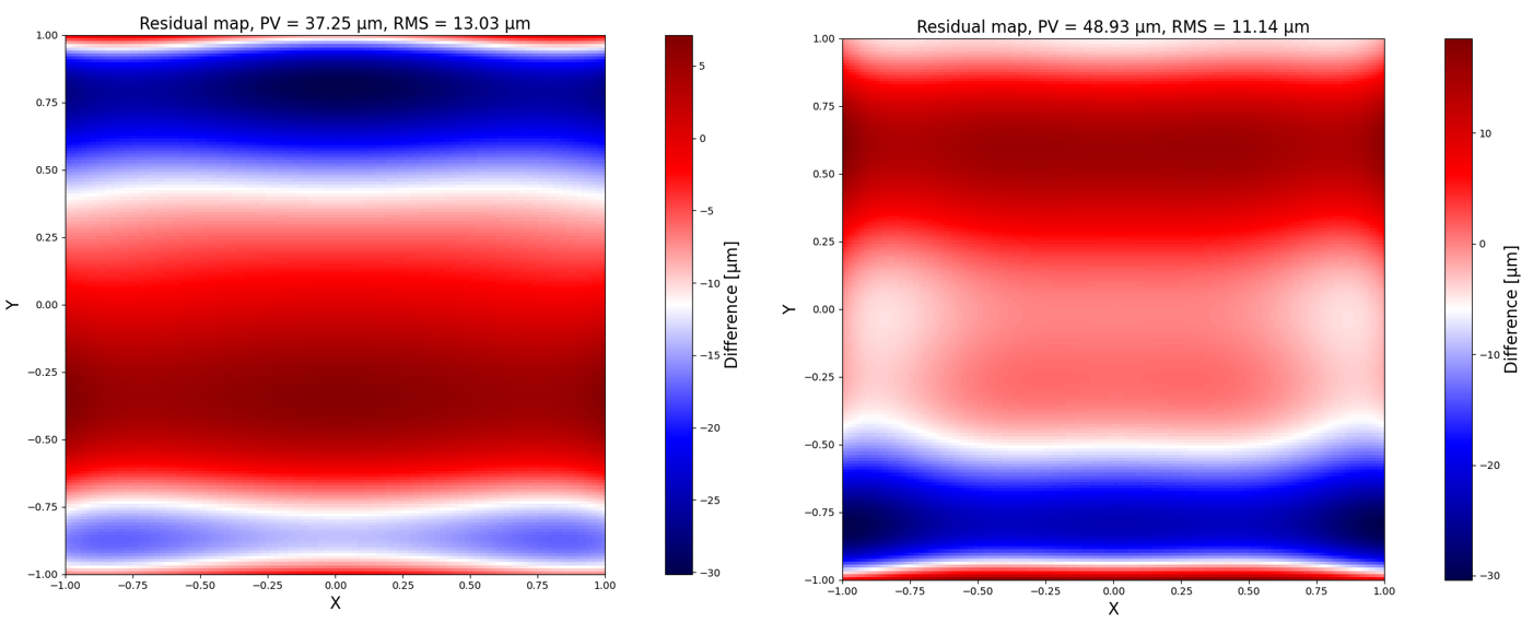
Figure 11: Residual (torus–freeform) image surface shape differences; errors dominated by low tens of microns.
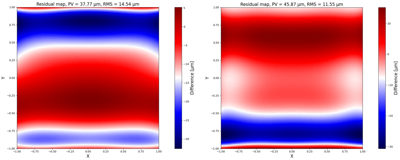
Figure 12: Residual (cylinder–freeform) differences, confirming adequacy of quadratic approximations for real image surface.
These residuals are on the order of typical detector flatness tolerances and thus insignificant for diffraction-limited or seeing-limited imaging above 0.05".
The principal result concerning performance is that the curved detector designs provide only a minor degradation relative to the flat baseline (quantified at ∼20% larger spot sizes for the cylindrical case) while enabling system simplification (reduced lens count, decreased manufacturing and alignment complexity) and significant cost reduction (approx. €7M at instrument scale from lens removal alone). The theoretical limit for image quality is set by the staircase pseudo-slit geometry, not the detector shape, so further relaxation is available with slit engineering. These findings, supported by rigorous analysis and simulation, provide a robust basis for system design decisions.
Adoption of the cylindrical design is currently preferred due to practical fabrication limitations; however, the toroidal option remains scientifically and technically attractive contingent on industry progress in curved focal plane technology.
Practical and Theoretical Implications
On a practical level, the study supplies a transferable analytical framework for integral field spectrograph focal surface determination, applicable to any high-multiplex visible/near-infrared system. The ability to reduce the optical complexity at scale—hundreds of cameras and thousands of elements—fundamentally alters cost, maintainability, and reliability in large astronomical spectrographs.
Theoretically, the decomposition of the focal surface into spatial and spectral curvature with explicit ties to specific aberration sources enables versatile optimization and rapid assessment of design tradeoffs. Future developments in detector and image slicer manufacturability may shift the risk calculus in favor of more aggressive curvature profiles, reducing reliance on pseudo-slit compensation.
In the context of the WST and other survey-class facilities, this architecture directly responds to the future “spectroscopic follow-up gap” that will follow imaging-driven discovery programs over the next decade.
Conclusion
The detailed optical and system engineering presented in this paper establishes a rigorous baseline for the WST IFS spectrograph and demonstrates, through both analytical and empirical channels, the beneficial impact of curved detector technology on instrument architecture, performance, and cost. The formal derivation of ideal detector shapes and the demonstrated feasibility of cylindrical sensors constitute a credible path forward for large-scale integral field spectroscopy. Ongoing advances in the production of curved detectors, and a systematic assessment of the pseudo-slit/image slicer interface, will further refine these designs and set the agenda for future ground-based spectrographs.