- The paper presents a rigorous channel characterization of FR3 C-V2B links in urban environments, comparing SNR and SINR trade-offs against sub-6 GHz and mmWave bands.
- It employs detailed ray-tracing with both ITU-R and realistic 3D CAD models to simulate interference effects and antenna array configurations in dense cityscapes.
- Findings reveal FR3's robust performance for cell-edge UEs and provide guidance for optimal BS density and frequency selection in future 6G urban deployments.
Characterization of FR3 Cellular Vehicle-to-Base Station Links in HighRise Urban Scenarios
Motivation and Context
The evolution of wireless communication networks is marked by the continuous search for higher capacity and reliability, with 6G technologies targeting demanding applications such as URLLC, mMTC, XR, and metaverse platforms. To address escalating data demands and deployment challenges in urban environments, the upper mid-band, designated as Frequency Range 3 (FR3: 7.125–24.25 GHz), has emerged as an attractive candidate. FR3 promises to balance the large bandwidth of mmWave (FR2) with the favorable propagation of sub-6 GHz (FR1), making it particularly relevant for cellular vehicle-to-base station (C-V2B) links in dense, high-rise cities. The technical objective of this paper (2604.03992) is to rigorously characterize downlink C-V2B performance across sub-6 GHz, FR3, and mmWave bands placed in realistic urban topologies, utilizing ray-tracing (RT) channel models augmented with accurate antenna array configurations.
Urban Modeling and Simulation Scenarios
The study employs both statistical (ITU-R) and detailed 3D CAD models of Dubai’s downtown to provide a realistic high-rise urban environment. Key urban layout parameters such as area ratio (α0), building density (β0), and height scale (γ0) are utilized for stochastic city configuration, while Blender-OSM tools furnish true-to-life geometries and material distributions. The RT tool Wireless InSite simulates signal propagation, permitting six reflections, one diffraction, and one transmission per path, thereby capturing the complex multipath and blockage dynamics typical of urban canyons.
Two interference regimes are analyzed:
- Interference-Free Scenario: Orthogonal scheduling eliminates inter-cell interference, isolating noise and propagation effects.
- Full-Interference Scenario: All BSs operate co-channel, maximizing inter-cell interference—a worst-case condition for SINR.
Wideband MIMO Channel Model and Antenna Deployment
A frequency-selective wideband MIMO channel model is adopted, where path delays, amplitudes, and phases are explicitly modeled per link. Uniform rectangular arrays (URA) at BSs and uniform linear arrays (ULA) on UEs ensure aperture scaling with frequency, maintaining equal transmitter aperture across bands for fair comparison. Maximum ratio transmission (MRT) and maximal ratio combining (MRC) optimize spatial processing at transmitter and receiver, respectively.
Directivity patterns for single elements and array configurations (2×2, 3×3, 5×5, 9×9 URA) are shown, illustrating the narrowing beamwidth and increasing gain as frequency and antenna count rise.
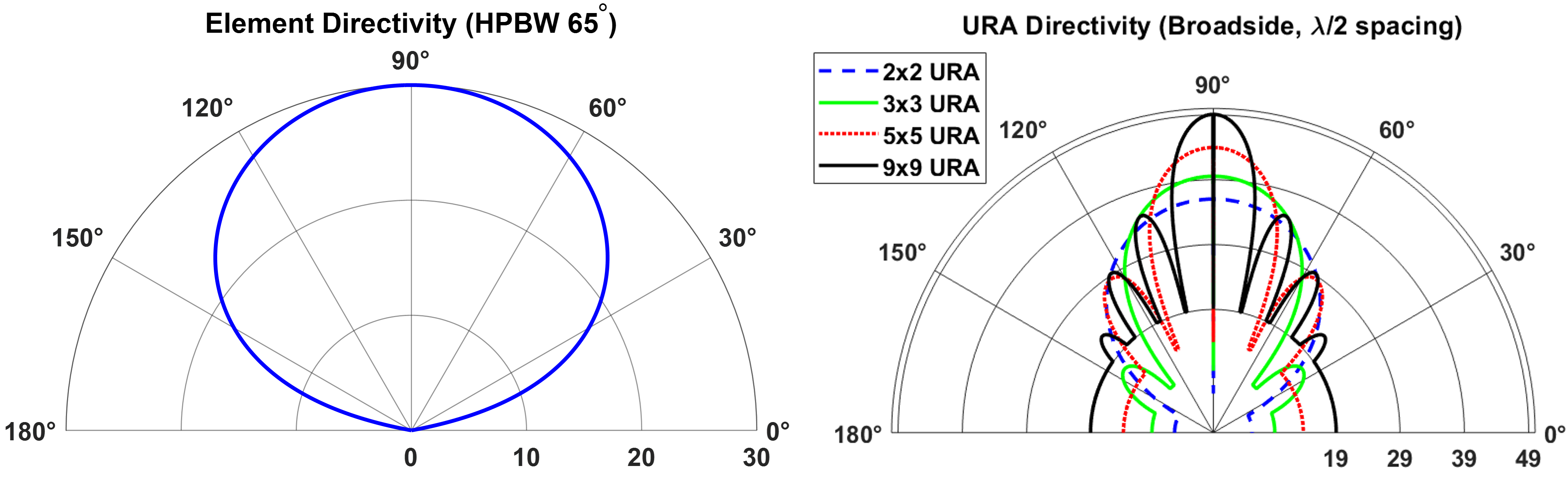
Figure 1: Directivity patterns for single element and BS antenna arrays (2×2, 3×3, 5×5, 9×9 URA) demonstrating frequency-dependent directivity.
SNR and SINR Statistical Characterization
Statistical evaluations are conducted using 370 UEs randomly placed, with results averaged over multiple urban deployments. The SNR and SINR are computed under both interference regimes, with all simulations performed using identical aperture and power settings across frequencies.
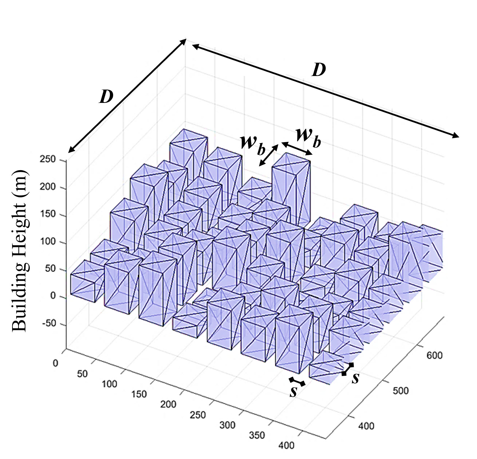
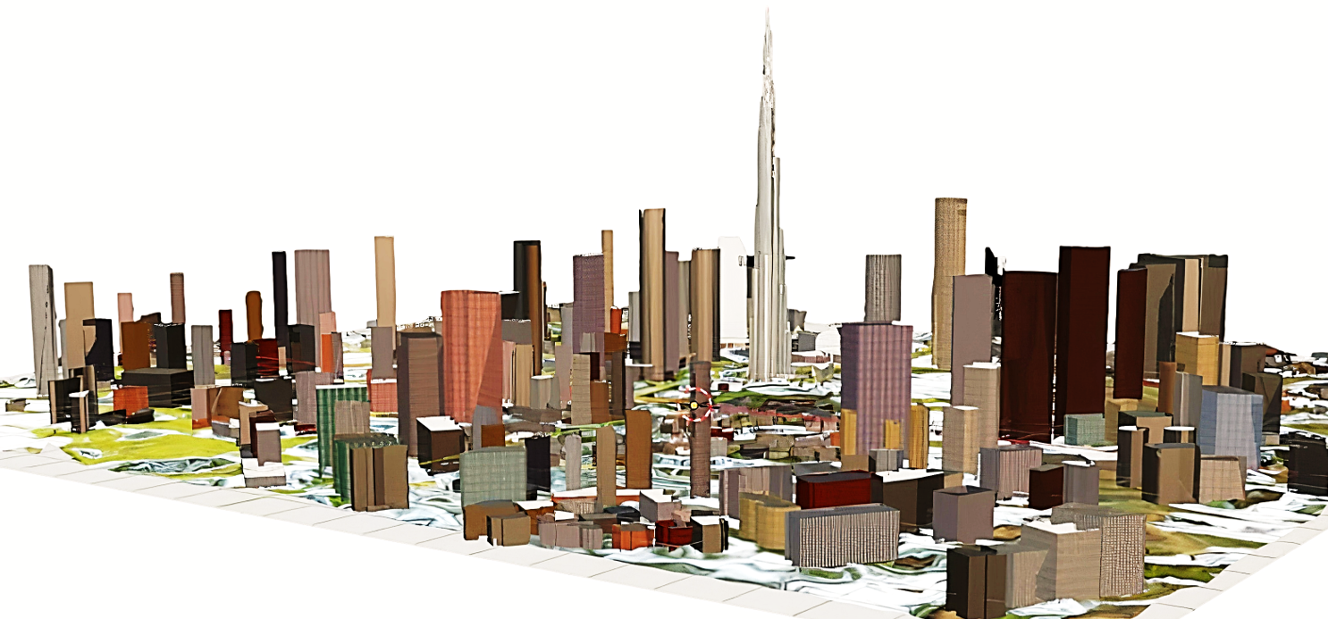
Figure 2: Generated city models and vehicle CAD model for simulation in ITU statistical and Dubai CAD environments.
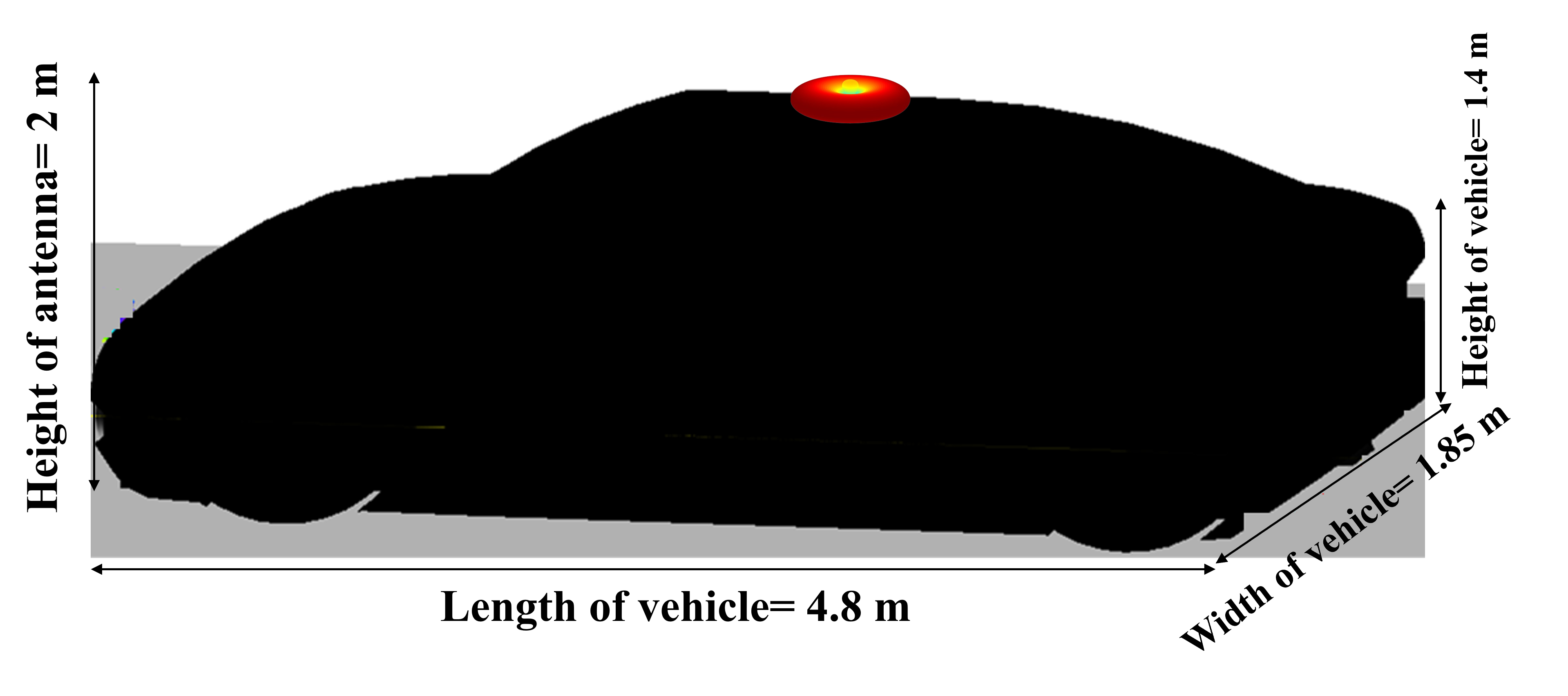
Figure 3: Vehicle CAD model illustrating antenna placement for C-V2B link analysis.
The cumulative distribution functions (CDFs) of SNR (interference-free) and SINR (full-interference) are presented for 4.6, 8.2, 15, and 28 GHz bands. Notable conclusions include:
- SNR: Lower frequencies consistently yield higher SNR due to reduced path loss and smaller noise power (bandwidth-dependent). FR3 demonstrates SNR comparable to sub-6 GHz at lower and upper CDF levels and superior to mmWave owing to its moderate bandwidth.
- SINR: For high CDF levels (upper 10%), higher frequencies outperform lower ones due to significant beamforming gains, which suppress interference. However, for low CDF levels (cell-edge UEs, below 10%), mmWave array gain cannot offset severe path loss, resulting in FR3 delivering higher SINR than mmWave, a bold claim directly contradicting common expectations of array gain dominance.
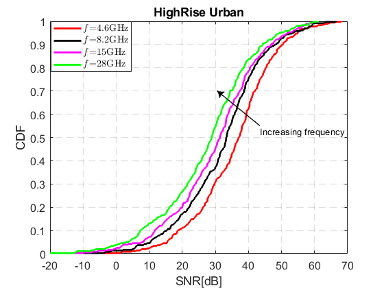
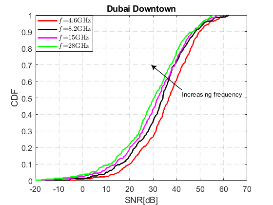
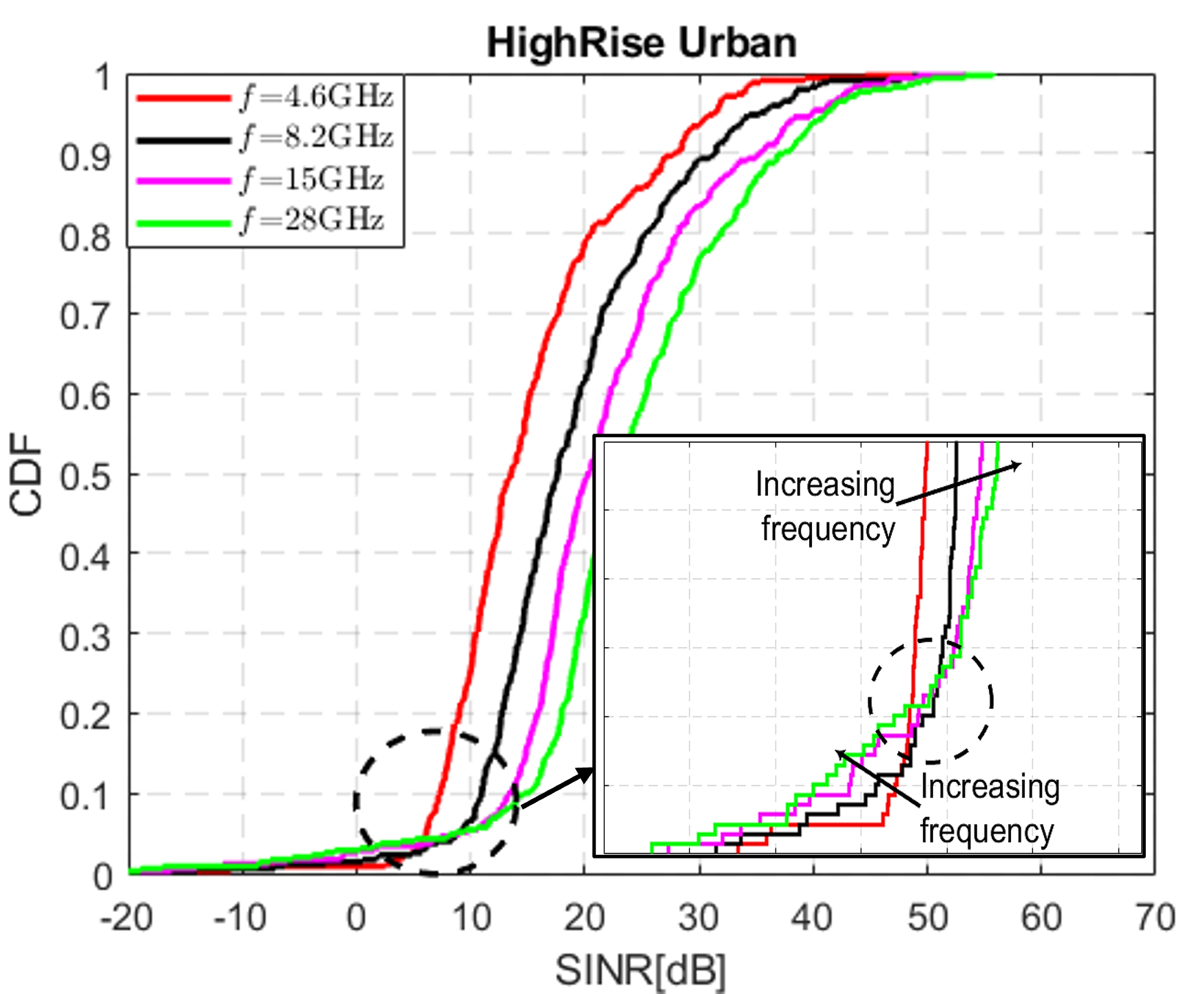
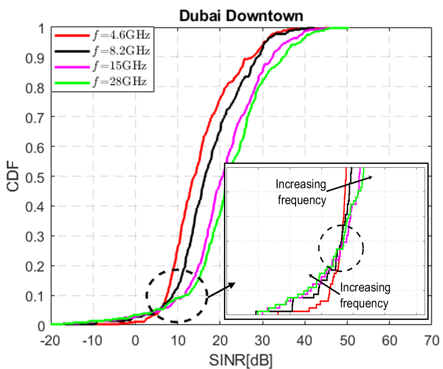
Figure 4: SNR and SINR CDFs under both ITU-generated and Dubai CAD models across bands in interference-free and full-interference scenarios.
Influence of BS Density on Coverage Probability
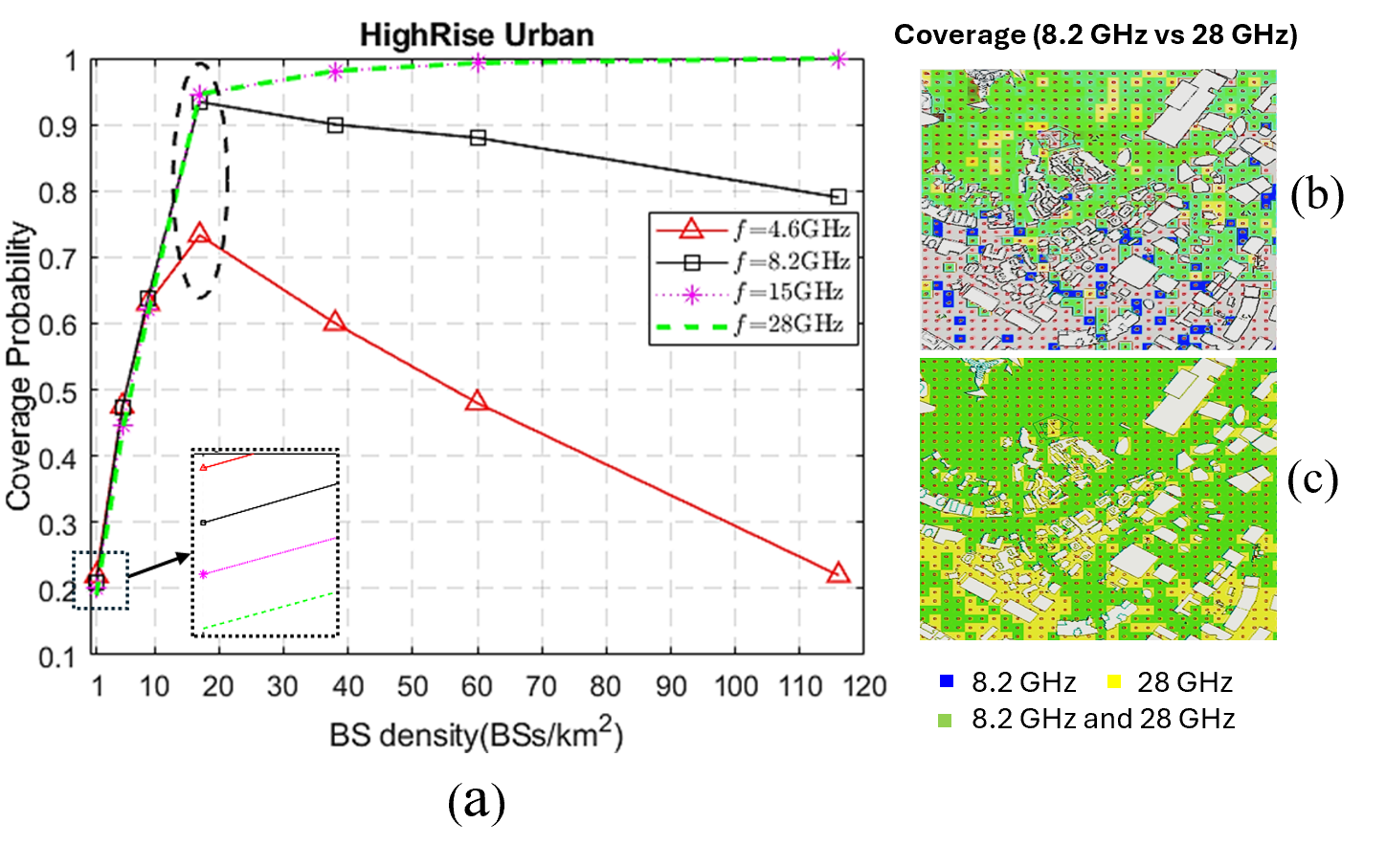
Coverage probability (fraction of UEs above SINR threshold) is investigated as a function of BS density for all bands in full-interference conditions. Results show:
Practical and Theoretical Implications
The results demonstrate the nuanced interplay between frequency-dependent path loss, beamforming, bandwidth-induced noise, and interference in dense urban deployments. FR3 frequencies provide a well-balanced channel profile:
- Cell-edge UEs: FR3 robustly sustains SINR, outperforming mmWave, regardless of the latter’s array gain.
- System Design: Optimal BS density and frequency selection depend on the propagation environment and expected interference regime; aggressive densification does not guarantee coverage gains in low-frequency bands.
The empirical findings suggest that 6G network operators should strategically leverage FR3, particularly in urban C-V2B scenarios where the superior trade-off between coverage and capacity can be exploited. The results highlight that mmWave’s additional array gain is insufficient to counteract path loss in typical urban cell-edge scenarios, and network planning should consider frequency-band, aperture scaling, and BS density jointly.
Conclusion
This work provides a rigorous channel characterization for FR3 C-V2B links in high-rise urban environments, demonstrating that FR3 offers optimal SNR/SINR performance balance compared to both sub-6 GHz and mmWave bands. The findings challenge conventional views on mmWave dominance, showing that array gain does not fully mitigate path loss for edge UEs. Practically, these insights inform BS density choices, frequency allocation, and spatial processing strategies for future 6G vehicular deployments. Theoretically, the study highlights the necessity of holistic channel modeling, combining geometry, interference, and antenna array scaling, to guide realistic system design. These observations are poised to influence both the standardization and practical deployment of 6G urban networks.