- The paper presents the innovative SBS design that achieves up to 70 msr solid angle acceptance at minimal scattering angles.
- It employs a unique dipole magnet with segmented iron ring shielding that effectively suppresses fringe magnetic fields and reduces background noise.
- Comprehensive field simulations and a modular detector setup validate the SBS performance for high-luminosity, forward-angle experiments.
Design and Implementation of a Forward-Angle Large-Acceptance Magnetic Spectrometer
Introduction
This paper presents the conceptual design, realization, and operational capabilities of the Super Bigbite Spectrometer (SBS), a large solid angle magnetic spectrometer constructed at the Thomas Jefferson National Accelerator Facility and optimized for high-luminosity experiments with forward scattering kinematics (2604.02136). The SBS addresses functional limitations of previous spectrometers, such as restricted minimum scattering angles and limited solid angle acceptance, particularly when targeting small-angle, high-Q2 electron scattering and nucleon recoil measurements critical for ongoing hadron structure studies.
Mechanical and Magnetic Design Considerations
The SBS features a large-aperture dipole magnet with a horizontal field orientation and a novel yoke design incorporating a horizontal slit for the beamline. This configuration enables placement of the spectrometer at a minimal distance (160 cm) from the interaction target, permitting an unprecedented solid angle acceptance of up to 70 msr at central angles as small as 15 degrees.
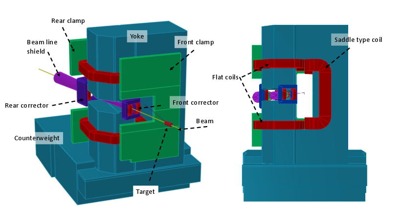
Figure 1: 3D and front views of the SBS dipole magnet, highlighting the horizontal slit and field clamp geometry.
The beamline slit is protected by a dual-layer magnetic shielding system, whose external component uniquely utilizes a set of iron rings rather than conventional pipe geometries. This solution mitigates saturation issues inherent in double-layer pipe shields, effectively suppressing the transverse field components that could otherwise perturb the primary beam, increase detector backgrounds due to low-energy electrons, and complicate high-precision measurements.
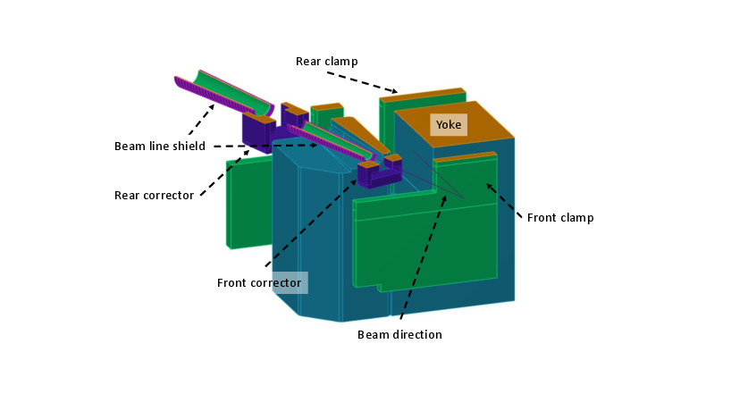
Figure 2: Cutaway visualization of the SBS magnet showing the beamline path and its outer ring-based shielding system.
To stabilize the substantial mass (100 tons) of the vertically oriented dipole in proximity to the target without losing solid angle, the spectrometer utilizes a cantilever configuration with a heavy counterweight, in preference to bulky conventional support structures.
Field Properties and Beamline Shielding
Comprehensive field simulations with the TOSCA/OPERA codes were used to refine the yoke and shielding geometry. The SBS gap field reaches 12 kG, while the field within the beamline slit is suppressed to $1$–$2$ G, a reduction by four orders of magnitude relative to the measurement region.
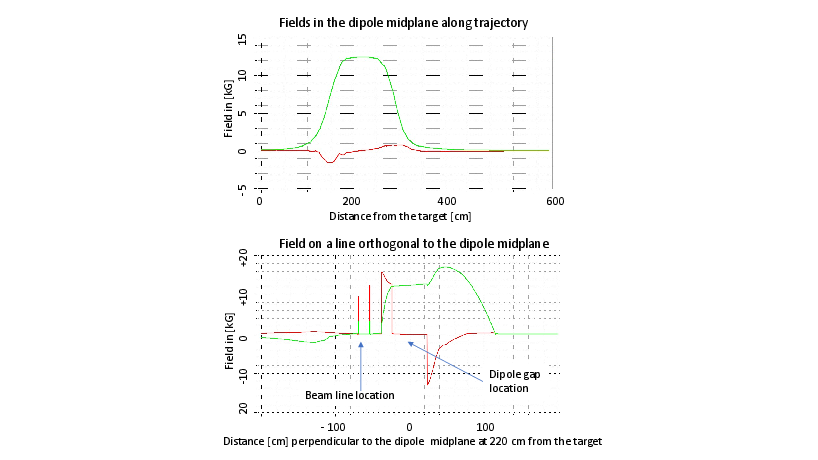
Figure 3: Longitudinal and transverse field components along the midplane and at a reference plane downstream, illustrating effective field suppression inside the shielded beamline region.
Corrective dipole coils positioned before and after the primary yoke, with independently powered left/right windings, further minimize integrated transverse fields (Bx). This keeps the beam deviation through the beam dump region below 2 cm for a 10 GeV electron beam, and reduces backgrounds from secondary particles. Passive shielding using segmented steel rings (AISI/SAE 1006) demonstrates substantial efficacy without the operational risks associated with active (solenoidal) compensation.
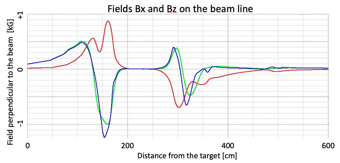
Figure 4: Measured Bx and Bz field components along the beamline, showing the effect of active dipole correctors and angular dependence of the residual transverse field.
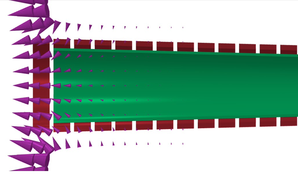
Figure 5: Vector field mapping near the beamline exit, showing local suppression and vector orientation achieved through the segmented iron ring shield.
Gap shims are used to increase field integral and tune acceptance for specialized experiments (e.g., form factor measurements), with up to a 25% increase observed for the GEp experiment configuration.
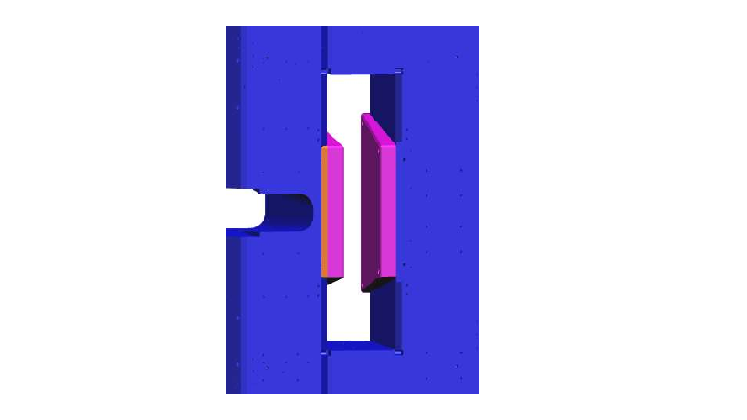
Figure 6: 3D rendering of yoke gap with pole shims installed for reduced acceptance operation (GEp setup).
The SBS maintains a relative momentum resolution parameterized as (0.3+0.03×p[GeV])%, dictated primarily by the field integral, GEM tracking resolution, and multiple Coulomb scattering in intervening materials. The spectrometer’s acceptance is nearly symmetric in the vertical plane, and for central angles near 15 degrees, SBS covers roughly 25% of the maximal kinematically allowed solid angle. The mechanical and field configurations accommodate operation at luminosities up to several 1038 cm−2/s, supporting a range of polarized and unpolarized targets.
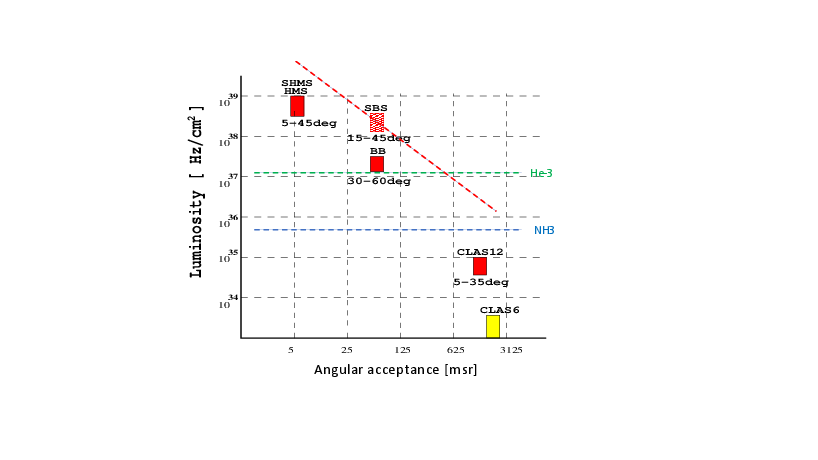
Figure 7: Usable luminosity versus spectrometer solid angle for JLab instruments; SBS offers superior acceptance·luminosty product at forward angles, especially relevant for polarized target experiments.
Detector Implementations
The open-geometry behind the dipole—facilitated by the vertical bend—accommodates modular detector packages optimized for specific experiments. Standard layouts include high-rate GEM trackers (coordinate resolution: 70 μm; front and rear arrays sandwiching a $56$-cm CH$1$0 block), and a large 1.8 m × 3.6 m hadron calorimeter ($1$10.75 ns time resolution for energetic protons). The modular CH$1$2 analyzer and RICH/proportional calorimeter extensions allow flexible deployment for polarization transfer, semi-inclusive DIS, and exclusive reaction measurements.
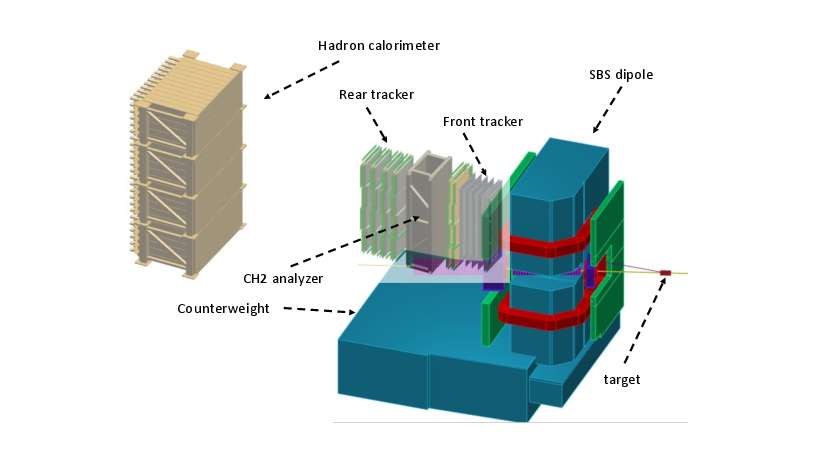
Figure 8: Full SBS spectrometer system as deployed in the GEp form factor ratio measurement, with annotated major detector components.
GEM layers are arranged with a strategic mix of strip angles to optimize straight trajectory finding under high occupancy, and the hadron calorimeter’s module design (steel-scintillator layers with fast wavelength shifting readout) enhances trigger selectivity and timing.
Practical and Theoretical Implications
The SBS demonstrates that forward-angle, high-luminosity measurements at momentum transfers up to 8 GeV/c can be achieved with large acceptance without incurring prohibitive backgrounds or compromising tracking performance. Passive field suppression methods can be engineered to suppress field leakage below thresholds critical for beam quality and detector performance, even in the presence of strong longitudinal and transverse fringe fields, thus relaxing constraints on target and detector placements. The design allows simultaneous operation of two-arm experiments with manageable cross-arm field crosstalk.
Applications span elastic form factor measurements, studies of generalized parton distributions, and semi-inclusive/DIS programs, with the configuration enabling high-statistics data acquisition required for low-analyzing-power polarization methods and rare reaction channels.
Conclusion
The SBS forward-angle spectrometer marks a significant advancement in magnetic spectrometer architecture for nuclear and hadronic physics, supporting solid angles up to 70 msr at minimal central angles and high luminosity environments. Its unique mechanical and magnetic innovations—especially the use of segmented iron ring shielding and active field correctors—demonstrate effective solutions for field suppression and background mitigation near the beamline. The system’s flexible detector arrays, robust acceptance, and operational stability position it as a central resource for current and future experiments requiring large acceptance, high resolution, and sustained high-luminosity operation (2604.02136).

