- The paper establishes a deterministic spatial upper bound on radiated power that is always achieved in the antenna boresight, irrespective of beamforming state.
- The paper demonstrates the use of coherent phasing in both two-element and Massive MIMO arrays with experimental OTA measurements showing deviations below 1 dB.
- The paper highlights a model-free bound approach that simplifies regulatory coexistence analysis and adjacent-band emission assessments in active antenna systems.
Spatial Upper Bound of Radiated Power in Active Antenna Systems
Introduction and Problem Statement
The migration to 5G and beyond has driven the adoption of Massive MIMO base stations equipped with Active Antenna Systems (AAS) utilizing digital beamforming to realize high spectral efficiency. While these architectures enable precise in-band directivity, they introduce notable complexities when evaluating unwanted radiated emissions, especially in scenarios that demand adjacent-band coexistence (e.g., with aeronautical altimeters). Conventional methods developed for passive antenna systems or weakly directive antennas often fail to offer both rigorous and tractable means for regulatory interference assessment with dynamically beamformed AAS. This work theoretically establishes the existence and properties of a deterministic spatial upper bound on radiated power for AAS—demonstrating that the maximum always occurs in the antenna boresight—regardless of frequency, signal type, or beamforming state.
Theoretical Framework: The Two-Element Array
The study begins with the analysis of a two-element antenna array along the y-axis, spaced by λ/2, under the assumption of ideal amplitude and phase calibration conforming with contemporary digital beamforming practice.
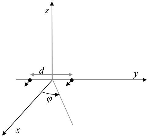
Figure 1: Two-element array positioned along the y-axis.
The array's radiation properties in the azimuthal plane are defined using standard 3GPP antenna models for the element, with the array factor modulated by a controllable excitation phase difference ΔΦ. When sweeping ΔΦ across the full [0,2π] interval, the peak attainable field in any direction achieves the same value, resulting in a maximum array factor magnitude of two (or +6 dB in power).
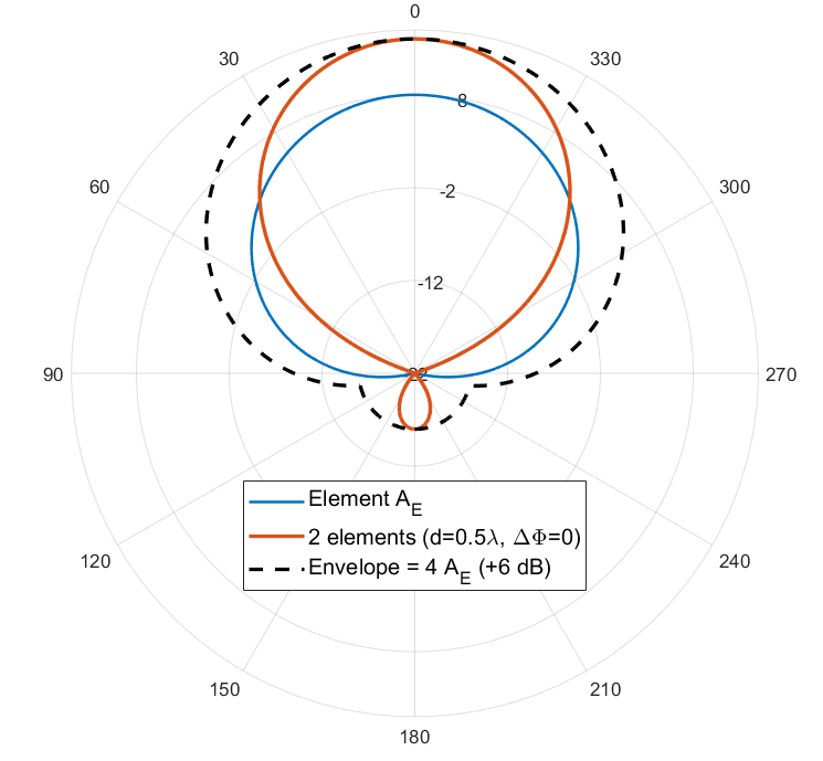
Figure 2: Two-element array pattern envelope.
This key result leads to the concept of a “spatial envelope”—the pattern upper bound—governed solely by the elementary radiator's angular response, offset by the coherent combining gain and independent of the instantaneous beam.
Spatial Upper Bound Mechanisms and Spectral Regions
The analysis divides the radiated spectrum into three regions dictated by the predominant signal component:
- In-band (Signal-dominated): The radiated fields from the two elements are fully coherent, yielding a directional Equivalent Isotropically Radiated Power (EIRP) envelope identical in shape to the single-element pattern but scaled by +6 dB.
- Third-order Distortion (IM3): Nonlinear intermodulation follows the same beamforming structure as the desired signal, with the same angular envelope.
- Noise-dominated: Here, the uncorrelated noise contributions sum incoherently, producing a spatial envelope following the radiator pattern with a +3 dB offset (power summation instead of field).
Irrespective of which component dominates, the maximal radiated field always aligns with the boresight due to coherent-phasing capabilities, presenting a deterministic upper bound.
Multi-User Transmission and Spatial Dispersion
Extending to two-user MIMO scenarios, each branch transmits a composite of user data, subjected to per-user phase gradients for independent beam steering. Nonlinear PA outputs then comprise both self-distortion and cross-intermodulation components:
- Self-distortion and Type-A cross-IM terms are beamformed with the parent signal direction,
- Type-B cross-IM terms generate beams in directions defined by specific linear combinations of user phase gradients, yielding up to four spatially dispersed maxima.
This mechanism inherently disperses the radiated distortion across more angles compared to the single-user case, reducing the peak EIRP in any given direction. The spatial upper bound, based on the single-user boresight case, remains valid and conservative in the multi-user scenario.
Generalization to Massive MIMO AAS
The theory generalizes to practical AAS architectures, where multiple elements are organized into sub-arrays—each treated as the radiating unit with independent RF chains and dual-polarization support. The maximum array factor is realized by phase selection that co-phases all sub-array contributions in any chosen direction, resulting in a spatial upper bound envelope contoured by the sub-array pattern.
Experimental Validation
OTA measurements were conducted on a commercial 3.5 GHz Massive MIMO antenna. The system was exercised under various excitation configurations (full power, DPD-enabled, 16 dB backoff), and both frequency and spatial characteristics of the radiated PSD were measured.
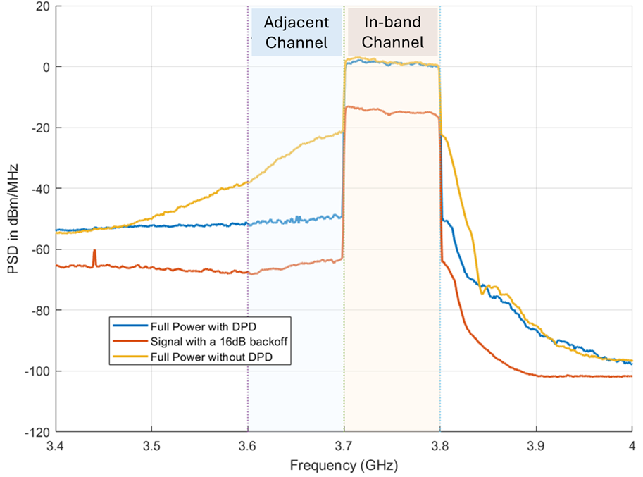
Figure 3: Measured boresight EIRP spectral density from 3.4 to 4.0 GHz for three configurations, showing in-band, IM3, and noise-dominated behavior.
The spatial (azimuth) distributions of both in-band and adjacent-band emissions were compared with the predicted spatial upper bounds.
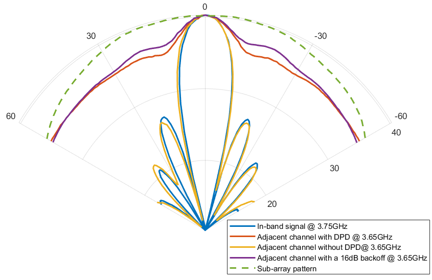
Figure 4: Azimuth cuts demonstrating spatial envelopes for in-band and adjacent emissions with and without DPD, plus 16 dB backoff.
Beam steering experiments for seven angles quantitatively confirmed that the measured EIRP never exceeded the theoretical bound at any steering angle or frequency, with maximum deviation under 1 dB.
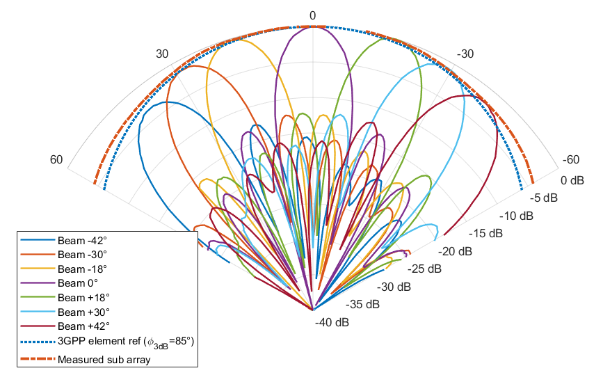
Figure 5: Validation of spatial upper bound for seven beam steering angles; deviation between bound and measurements is consistently below 1 dB.
Multi-user experiments revealed the characteristic spatial power dispersion—multiple maxima at predicted directions due to IM3 generation—validating analytical predictions for both in-band and adjacent-band radiation.
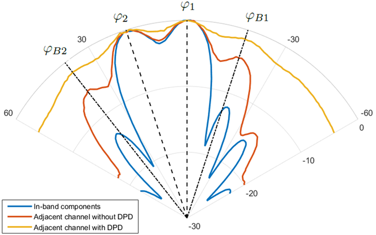
Figure 6: Multi-user scenario showing spatial dispersion of in-band and OOB emissions normalized to the in-band boresight level.
Implications for Regulatory and Coexistence Analysis
- Model-Free Bound: The spatial upper bound requires only two physical inputs: the measured boresight spectral density and the characterized sub-array (or element) pattern. There is no need for explicit modeling of spatial correlation between antennas or the statistics of nonlinear distortion.
- Role of DPD: DPD not only improves linear ACLR but also reduces the spatial concentration of OOB emissions by suppressing coherently beamformed IM3, facilitating a flatter radiation envelope.
- Conservative, Practical Engineering Tool: The framework allows deriving a conservative, regulatory-suitable emission bound without requiring simulation or enumeration over all possible beamforming states or power amplifier non-idealities. With uncertainty margins (e.g., +1.3 dB for OTA, +3 dB for OOB), it is compliant with 3GPP testing standards.
Theoretical and Practical Impact
The primary theoretical result is that the maximum radiated power from an AAS—with arbitrary beamforming, frequency, or nonlinear signal component—is always realized in boresight and determined by the sub-array pattern upper envelope. Multi-user transmission further reduces the peak radiated power per spatial direction. This finding significantly simplifies coexistence studies and regulatory assessment, as it decouples detailed internal AAS state from worst-case OOB emission potential.
Future work may include rigorous formalization of the multi-user K-case, extension to highly nonlinear amplifiers, and optimization of DPD for OOB emission spatial uniformity. Additionally, there are potential ramifications for the design of AAS system-level EMC and spectrum sharing regimes in dense multi-service environments.
Conclusion
This study rigorously establishes and experimentally validates that the radiated power from beamformed AAS is bounded by a deterministic spatial envelope, maximized in boresight and governed only by the elementary radiator pattern. The bound holds across signal regimes (useful, IM3, noise), arbitrary beamforming states, and user configurations. The methodology, grounded in physical measurement and independent of complex correlation or distortion modeling, provides a conservative, practical tool for regulatory coexistence assessment in advanced radio systems.