MiCADangelo: Fine-Grained Reconstruction of Constrained CAD Models from 3D Scans
Abstract: Computer-Aided Design (CAD) plays a foundational role in modern manufacturing and product development, often requiring designers to modify or build upon existing models. Converting 3D scans into parametric CAD representations--a process known as CAD reverse engineering--remains a significant challenge due to the high precision and structural complexity of CAD models. Existing deep learning-based approaches typically fall into two categories: bottom-up, geometry-driven methods, which often fail to produce fully parametric outputs, and top-down strategies, which tend to overlook fine-grained geometric details. Moreover, current methods neglect an essential aspect of CAD modeling: sketch-level constraints. In this work, we introduce a novel approach to CAD reverse engineering inspired by how human designers manually perform the task. Our method leverages multi-plane cross-sections to extract 2D patterns and capture fine parametric details more effectively. It enables the reconstruction of detailed and editable CAD models, outperforming state-of-the-art methods and, for the first time, incorporating sketch constraints directly into the reconstruction process.
Paper Prompts
Sign up for free to create and run prompts on this paper using GPT-5.
Top Community Prompts
Explain it Like I'm 14
What is this paper about?
This paper introduces MiCADangelo, a new AI method that turns 3D scans of real objects into editable CAD models. CAD (Computer-Aided Design) models are the “blueprints” designers use to build, change, and manufacture things. The key idea is to copy how human designers work: look at 2D slices of a 3D object, draw clean 2D sketches with rules (called constraints), and then pull those sketches into 3D shapes using an operation called extrusion. MiCADangelo does this automatically and captures fine details while keeping the model easy to edit later.
What questions did the researchers ask?
They focused on three simple questions:
- How can we convert a rough 3D scan (like a digital “photo” of an object) into a clean, editable CAD model?
- Can we recreate not just the shapes, but also the design rules (constraints) that keep the model tidy and easy to modify?
- Can we match the original object’s shape closely, including small, tricky details, and still work well with standard CAD software?
How did they do it?
To make the process easy to understand, think about slicing a loaf of bread to see its inside layers.
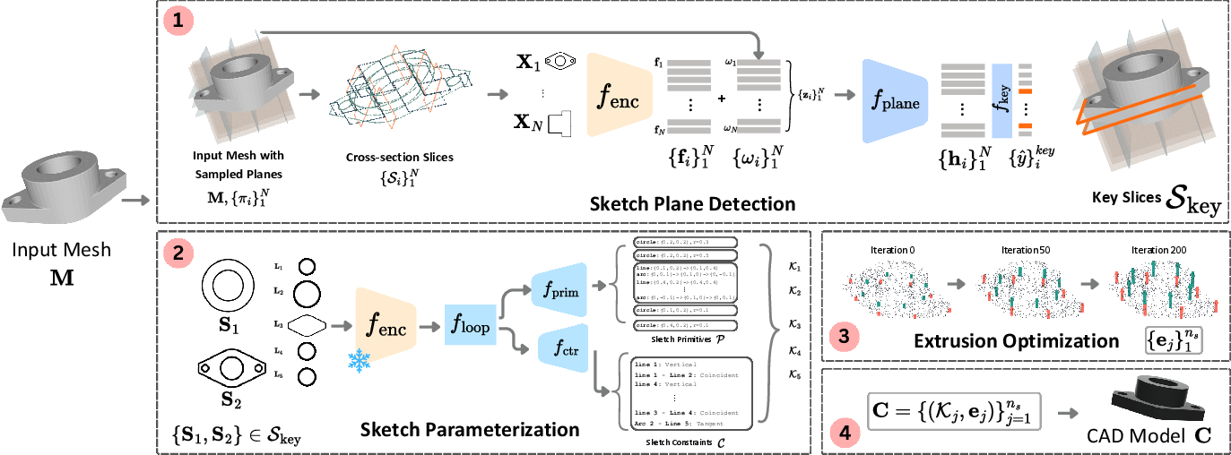
Step 1: Finding useful slice planes
- The system takes the 3D scan and slices it in many places along the X, Y, and Z directions (like cutting bread vertically, horizontally, and lengthwise).
- Each slice looks like a 2D outline of the object at that location.
- An AI model picks the “key” slices that best capture the important parts to sketch.
Step 2: Turning slices into sketches with constraints
- For each key slice, the system finds closed outlines (loops) and turns them into simple 2D drawings.
- It then identifies basic sketch pieces (called primitives), like lines, circles, and arcs, and adds constraints—rules such as “these two lines must stay parallel” or “this line is vertical.”
- Constraints matter because they protect the design’s intent: if you move one point later, the model stays neat and consistent.
Step 3: Extruding sketches into 3D parts
- Extrusion is like using a cookie cutter: you take a 2D shape and push it in a direction to give it thickness.
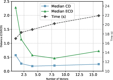
- The system figures out how far to extrude each sketch so the resulting 3D parts match the scan as closely as possible.
- It does this by adjusting the extrusion length to minimize the difference between the extruded shape and the original 3D scan.
Putting it all together
- The system combines all the extruded parts into a final CAD model.
- The model is parametric, meaning it’s controlled by numbers (like lengths and radii), and it has constraints, so you can edit it safely in CAD software.
Here are a few key terms in simple words to help:
- Parametric: the shape is controlled by adjustable numbers, so it’s easy to change later.
- Constraint: a rule that keeps things in order (like “these lines must stay perpendicular”).
- Extrusion: turning a flat shape into a 3D one by pushing it along a direction.
- Cross-section: a 2D slice of a 3D object.
What did they find and why it matters?
The researchers tested MiCADangelo on popular CAD datasets (DeepCAD and Fusion360), and also on real, messy scans (CC3D). Their main findings:
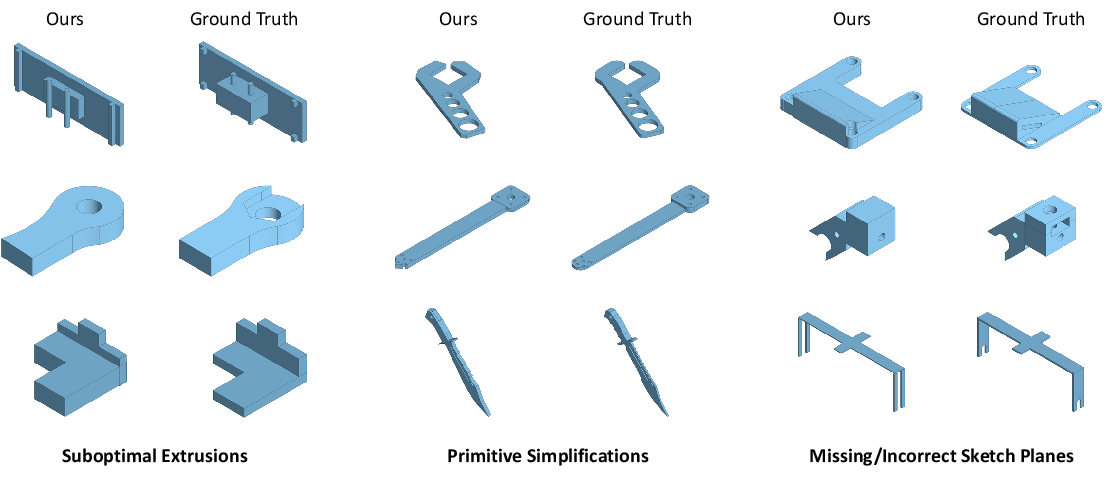
- It matches the original shapes very closely, including fine, detailed features that other methods often miss.
- It produces fully editable CAD models with constraints, which is something earlier methods didn’t handle.
- It stays robust on real-world scans that have noise and imperfections.
- When you adjust the sketch after reconstruction (like moving a point), the constraints help the model update properly without falling apart. This shows it captures the designer’s intent, not just the shape.
In short, MiCADangelo is more accurate, more editable, and more practical for real design work than previous approaches.
What could this change in the real world?
- Faster reverse engineering: Companies can scan parts they already have and quickly create clean, editable CAD models to improve or customize them.
- Easier editing: Because the models include constraints, changing one part of the design doesn’t ruin the rest—it stays consistent, like a well-behaved blueprint.
- Better integration with CAD tools: The output fits standard CAD workflows, so engineers and designers can keep using their favorite software.
- More reliable results: It works better on complex shapes and in-the-wild scans, which saves time and reduces errors.
Limitations and future improvements:
- Right now, the method mainly uses extrusion; other CAD operations (like revolutions or complex curves such as B-splines) aren’t supported yet.
- It works best when extrusion directions line up with the main axes; more flexible directions are a future goal.
- Adding more sketch types and operations would make it even more powerful.
Overall, MiCADangelo moves scan-to-CAD closer to how real designers think and work, making the process more accurate and much more useful.
Knowledge Gaps
Below is a single list of concrete knowledge gaps, limitations, and open questions that remain unresolved by the paper. Each item is framed to be actionable for follow-up research.
- Limited operation repertoire: the pipeline supports only extrusions; no handling of common CAD operations such as revolve, sweep, loft, shell, fillet/round, chamfer, pattern/array, hole features, or draft angles.
- Axis-aligned slicing only: cross-sections are sampled along fixed x/y/z axes, potentially missing oblique features, revolved geometry, or features best revealed by adaptively oriented planes.
- Extrusion depth/type heuristics: “cut” features are treated as infinite cuts and “new” features have a single global depth per loop; there is no inference of finite cut depths, extrude-to-next/up-to-surface terminations, or side-dependent termination conditions.
- Per-loop independence: loops are parameterized and optimized independently, with no modeling of inter-loop or inter-sketch relationships (e.g., equal radii across loops, concentric features across planes, symmetry), which are common in CAD design intent.
- No operation ordering model: extruded parts are “assembled” without learning or inferring a robust construction sequence; ordering matters for Booleans and can change outcomes.
- Constraint scope and solver integration: constraints are predicted but there is no integration with a CAD constraint solver to detect and resolve under-/over-constrained or inconsistent sketches, nor reporting of solver satisfaction rates.
- Missing dimensional constraints: the method predicts topological/geometric constraint types (e.g., parallel, tangent) but does not infer explicit dimensional parameters as constraints (e.g., fixed distances, angles, radii) or tolerances, limiting editability and fidelity.
- Quantized parameterization: primitive and constraint parameter spaces are discretized; the precision-accuracy tradeoffs, quantization error, and potential benefits of continuous regression or refinement are not evaluated.
- Raster-based sketch inference: relying on 128×128 rasterized loop images can lose precision on small/fine features; there is no ablation on image resolution, anti-aliasing strategies, or vector-native representations for sketches.
- Plane detection supervision dependency: key-slice labels are derived from DeepCAD in a supervised manner; there is no unsupervised or self-supervised alternative for real-world scans without labels, nor analysis of label generation robustness.
- Generalization of constraints from SketchGraphs: constraints are learned on 2D sketch datasets not originating from cross-sections; the domain gap between design sketches and scan-derived slices is not quantified, and constraint faithfulness to original design intent is unvalidated.
- Constraint accuracy metrics: there is no explicit evaluation of constraint prediction accuracy (precision/recall per constraint type), constraint graph correctness, or editability audits beyond a limited single-extrusion perturbation study.
- Extrusion fit objective: the point-to-vector distance objective with a hard nearest-vector selection is potentially non-smooth; there is no discussion of using differentiable soft-min, SDF-based losses, or surface-aware objectives to improve stability and fit.
- Direction and orientation inference: extrusion directions are tied to plane normals and slicing is axis-aligned; the method cannot select arbitrary oriented planes or directions that better match true features.
- Handling of noisy or incomplete cross-sections: the approach assumes closed loops; robustness to open contours, gaps, or topological artifacts in real scans (holes, occlusions, non-manifold intersections) is not systematically addressed.
- Topology and BRep validity: there is no analysis of resultant BRep watertightness, Boolean robustness, or topology correctness (e.g., self-intersections, sliver faces) after assembling multiple extrusions.
- Scale and units: slices are normalized to unit boxes with stored normalization parameters; there is no explicit analysis of how absolute scale and units are preserved in the final CAD, or of scale sensitivity during learning/inference.
- Inter-sketch constraints: constraints are intra-sketch; cross-sketch constraints (e.g., alignment/concentricity across planes or features) are not inferred, limiting multi-step design intent capture.
- Feature classification by nesting parity: “new” vs “cut” determination via loop parity may fail on complex cross-sections; no study quantifies misclassification and its impact on reconstruction.
- Sequence-level evaluation: the method reports geometric metrics but lacks program-level metrics that assess correctness of the recovered design sequence, feature hierarchy, and constraint graph relative to ground-truth CAD histories.
- End-to-end runtime and scalability: there is no comprehensive profiling (per stage and overall), memory analysis, or scaling behavior w.r.t. number of slices, loops, or model complexity.
- Mesh-only input assumption: the pipeline requires a mesh; many scanners output point clouds; there is no integrated surface reconstruction or direct point-cloud handling nor a study of how meshing quality affects reconstruction.
- Limited test-time editing study: the editability experiment is restricted to single-extrusion sketches synthesized from SketchGraphs; multi-extrusion, multi-sketch edit propagation and constraint solver stability remain unexplored.
- Real-world robustness boundaries: while CC3D results are promising, the failure modes on diverse real scans (varying noise levels, materials, reflectance, partial views) and domain adaptation strategies are not analyzed.
- Data and label generation transparency: details on deriving key-plane labels and synthetic augmentation for cross-sections are deferred to supplementary; replicability and sensitivity to these choices remain open.
- No human-in-the-loop assessment: there is no user study with CAD professionals quantifying whether inferred constraints and sequences align with typical design intent and whether the resulting models are practically editable in CAD software.
Practical Applications
Immediate Applications
Below are actionable, near-term use cases that can be deployed with moderate integration effort, given MiCADangelo’s current capabilities (extrusion-based, constraint-aware reconstruction from scans of mostly prismatic/mechanical parts).
- Scan-to-parametric CAD for MRO and spare parts digitization
- Sectors: Manufacturing, aerospace MRO, automotive aftermarket, industrial equipment
- What it enables: Convert 3D scans of legacy or vendor-supplied parts into editable, constrained parametric CAD models to accelerate repair/replacement, varianting, and re-sourcing
- Potential tools/products/workflows:
- “Scan-to-Parametric CAD” plugin for SolidWorks/Fusion 360/Onshape/FreeCAD
- Integrated pipeline with Artec/other scanners → MiCADangelo → CAD kernel for constraint solve → STEP export
- Service-bureau workflow for quick turnaround parametric deliverables (not just tessellated meshes)
- Assumptions/dependencies:
- Parts predominantly representable with extrusions; limited freeform geometry
- Reasonable scan quality (coverage, noise, holes) and basic alignment to canonical axes or pre-alignment step (e.g., PCA/ICP)
- Access to a CAD kernel/solver that honors predicted constraints
- Rapid varianting of legacy/mechanical components
- Sectors: Consumer products, industrial machinery, robotics hardware
- What it enables: Use inferred sketch constraints (e.g., orthogonality, parallelism, tangency) to safely edit dimensions/relations for quick design variants while preserving design intent
- Potential tools/products/workflows:
- “Constraint-aware Parametric Retrofitting” feature in CAD
- Template-based customization (hole patterns, bosses, cutouts) from scanned baselines
- Assumptions/dependencies:
- Edits remain consistent with extrude-dominant feature structure
- Manual review of constraints for critical parts and tolerances
- Constraint-aided dimensional metrology from scans
- Sectors: Manufacturing QA/QC, metrology
- What it enables: Automatically derive editable baselines with constraints and compare critical dimensions to scan data; use edge- and surface-level error metrics (e.g., ECD, CD) for tolerance checks
- Potential tools/products/workflows:
- Metrology plugins: “Constraint-aware Deviation Maps” with dimensional callouts
- Automated QA reports showing constraint-preserving differences
- Assumptions/dependencies:
- Calibrated scanners; controlled measurement setups
- Tolerance policy and acceptance criteria defined by QA standards
- Digitization and cleanup of mesh archives into CAD for PLM
- Sectors: Enterprise PLM, digital thread/digital twin initiatives
- What it enables: Convert historical mesh libraries into editable, searchable parametric models; add constraints for design intent capture and downstream reuse
- Potential tools/products/workflows:
- Batch “Mesh-to-Parametric” conversion pipelines integrated with PLM/PDM systems
- Automated tagging by feature/constraint patterns for retrieval
- Assumptions/dependencies:
- Reasonable mesh fidelity; extrude-centric parts see highest ROI
- Compute resources for batch processing; human-in-the-loop validation on exceptions
- Robotics fixture and gripper design from scanned workpieces
- Sectors: Robotics (industrial/warehouse), automation
- What it enables: Generate constrained CAD of workpieces from scans to accelerate fixturing and end-effector design (extruded pads, jaw faces, nests)
- Potential tools/products/workflows:
- “Scan-to-Gripper-Fixture” assistant that outputs parameterized jaws/fixtures
- Integration with robot cell CAD and simulation tools
- Assumptions/dependencies:
- Workpieces approximable by extrusions or containing prismatic features
- Manual finishing for complex non-extruded geometries
- Education and training on constraints and design intent
- Sectors: Education, workforce development
- What it enables: Teaching reverse engineering and constraint systems via cross-sections and sketch inference; visualize how constraints propagate edits
- Potential tools/products/workflows:
- FreeCAD-based teaching modules showing constraint effects under edits
- Interactive tutorials comparing unconstrained vs. constrained edits
- Assumptions/dependencies:
- Classroom access to scans and CAD software; curated part sets suitable for extrusion
- Benchmarking research on constrained sketch inference
- Sectors: Academia (CAD, vision, geometry processing)
- What it enables: Evaluate plane detection, sketch+constraint inference, and differentiable extrusion; extend datasets and metrics
- Potential tools/products/workflows:
- Open-source baselines for constrained reconstruction and cross-section selection
- Protocols for stress-testing on noisy scans (e.g., CC3D-like artifacts)
- Assumptions/dependencies:
- Dataset availability (DeepCAD, Fusion360, SketchGraphs) and standardized preprocessing
- Access to CAD kernels for robust constraint validation
- Maker and SME scan-to-print with editability
- Sectors: Makerspaces, small businesses, repair shops
- What it enables: Convert a scan to a parametric model with constraints, quickly adjust key dimensions, then export to STL/STEP for fabrication
- Potential tools/products/workflows:
- Lightweight web app: upload scan → get constrained CAD → dimension edit → export
- “Constraint-preserving Scaling and Fitting” for replacement parts
- Assumptions/dependencies:
- Consumer-grade scanners produce sufficient quality for prismatic parts
- Manual tweaking for best fit; extrusion limits acknowledged
- AEC-adjacent profile reconstruction (select cases)
- Sectors: AEC (MEP components, extruded profiles, frames)
- What it enables: Recover parametric profiles (channels, frames, ducts) from scans where extrusion is dominant
- Potential tools/products/workflows:
- “Profile-from-Scan” tool for libraries of standard sections with editability
- Assumptions/dependencies:
- Limited to components well-approximated by extrusions; not suited for freeform architecture
- Alignment to building coordinates or profiles required
Long-Term Applications
The following use cases require further research/development (e.g., non-extrusion features, splines, arbitrary orientations), larger-scale validation, or broader ecosystem integration.
- Full-feature CAD reconstruction beyond extrusions
- Sectors: Mechanical CAD, automotive, aerospace
- What it enables: Add revolve/sweep/loft/patterns/fillets/chamfers; B-splines/NURBS for freeform; multi-operation histories with robust constraint solve
- Potential tools/products/workflows:
- “Generalized Scan-to-Feature Tree” with design history and editable constraints
- Hybrid learning + analytic fitting for high-order surfaces
- Assumptions/dependencies:
- Enriched datasets with labeled non-extrude operations and constraints
- Stronger geometric kernels and constraint solvers integrated into the pipeline
- Arbitrary orientation and multi-axis feature inference
- Sectors: Advanced manufacturing, robotics, tooling
- What it enables: Detect non-axis-aligned sketch planes and directions; handle compound angle extrusions and multi-axis machining features
- Potential tools/products/workflows:
- Orientation-invariant slice sampling and plane proposals (PCA/learning-based)
- Multi-directional, differentiable feature fitting (not only along plane normals)
- Assumptions/dependencies:
- Improved plane detection and robust orientation estimation under noise
- Expanded training distributions with diverse orientations
- Real-time in-line inspection and closed-loop manufacturing
- Sectors: Manufacturing QA, smart factories
- What it enables: On-the-fly parametric reconstruction from line-scanners/CT, automatic deviation reporting, instant feedback to machining/printing parameters
- Potential tools/products/workflows:
- Edge-deployable, accelerated MiCADangelo (GPU/FPGA) integrated with MES
- Closed-loop controllers adjusting processes based on constraint-preserving deviations
- Assumptions/dependencies:
- Low-latency scanning and compute; robust handling of partial scans
- Certification for production QA in regulated industries
- Brownfield digital twins with parametric fidelity
- Sectors: Energy, oil & gas, process industries, heavy industry
- What it enables: Parametric reconstruction of installed assets (fixtures, pipe supports, frames) to build editable digital twins and enable retrofit simulation
- Potential tools/products/workflows:
- Plant-scale scan segmentation → per-object parametric reconstruction → PLM sync
- Constraint-driven “what-if” simulations for retrofits and clearances
- Assumptions/dependencies:
- Robust segmentation; varied feature sets; handling occlusions and clutter
- Integration with asset management systems and twin platforms
- AR-guided field repair and right-to-repair enablement
- Sectors: Service/maintenance, consumer electronics repair
- What it enables: Mobile scan of a failed component → parametric reconstruction → on-device suggestions for edits and 3D-printable substitutes
- Potential tools/products/workflows:
- Smartphone AR app with on-device or cloud inference; parametric presets for common parts
- Assumptions/dependencies:
- Mobile-grade scanning quality; simplified constraints for real-time usage
- Policy and IP considerations around reverse engineering and part substitution
- Certified reverse engineering workflows for regulated sectors
- Sectors: Aerospace, medical devices, automotive safety parts
- What it enables: Standardized, auditable pipelines that trace constraints, edits, and verification metrics; conformity to standards
- Potential tools/products/workflows:
- “Constraint Traceability and Audit” modules; model provenance and versioning
- Validation suites aligning with industry standards (e.g., AS9100, ISO 13485)
- Assumptions/dependencies:
- Formal verification of constraint correctness and tolerance compliance
- Acceptance by regulators and certification bodies
- Patient-specific parametric medical device design
- Sectors: Healthcare (orthotics, prosthetics, dental appliances)
- What it enables: From patient scans to constrained parametric models that clinicians can adjust safely (constraints enforce anatomical relationships/clearances)
- Potential tools/products/workflows:
- Clinical CAD assistants with constraint templates for specific anatomies
- Assumptions/dependencies:
- Support for freeform, spline-heavy geometries; biocompatible constraints/clearances
- Regulatory approval; privacy-secure data handling
- Autonomous manipulation and simulation from on-the-fly parametric models
- Sectors: Robotics, logistics
- What it enables: Robots reconstruct editable parametric models of novel objects to infer graspable features, simulate contacts, and plan robust interactions
- Potential tools/products/workflows:
- Perception-to-CAD-to-simulation loops; constraint-aware grasp planning
- Assumptions/dependencies:
- Robust real-time reconstruction under occlusions; generalization beyond extrusions
- Tight integration with physics engines and task planners
- Marketplaces and standards for constraint-rich reverse-engineered parts
- Sectors: Platforms, procurement, supply chain
- What it enables: Exchange of parametric parts with documented constraints and editability; better interoperability than mesh-only models
- Potential tools/products/workflows:
- Constraint-aware STEP extensions and metadata; trust and provenance systems
- Assumptions/dependencies:
- Industry agreement on schemas and IP protection/watermarking for reverse-engineered CAD
- Legal/policy frameworks for compliant sharing
- Generative co-design with constraint feedback from scans
- Sectors: Software, design automation
- What it enables: Combine generative CAD (sketch+constraint LLMs) with scan-derived constraints to propose manufacturable redesigns with preserved design intent
- Potential tools/products/workflows:
- “Constraint-in-the-Loop” co-pilot that suggests variants consistent with scanned baselines
- Assumptions/dependencies:
- Stronger joint training on sketches, constraints, features, and manufacturability rules
- Human-in-the-loop governance for safety and IP
- Sustainability and remanufacturing analytics
- Sectors: Circular economy, sustainability
- What it enables: Quickly parametrize harvested components from e-waste/returns; assess fit-for-reuse via constraint-preserving deviation analysis; redesign for reuse
- Potential tools/products/workflows:
- Remanufacturing triage tools; dimensional compliance scores tied to parametric baselines
- Assumptions/dependencies:
- Handling of heterogeneous, damaged scans; scalable batch processing
- Integration with sustainability reporting and traceability systems
Notes on feasibility across all long-term items:
- Requires support for non-extrusion features and spline-based primitives
- Better robustness to real-world noise, partial scans, and arbitrary orientations
- Standardized datasets with constraints and full feature histories for training/validation
- Deeper integration with CAD kernels, solvers, PLM/MES, and certification ecosystems
Glossary
- Boolean operations: Set-theoretic operations used to combine or subtract solid primitives (e.g., union, intersection, difference) in solid modeling. Example: "using Boolean operations over primitives"
- Boundary Representation (BRep): A precise solid modeling format that encodes geometry via surfaces, edges, and vertices along with their topological relationships. Example: "Boundary Representation (BRep) reconstruction"
- B-splines: Smooth, piecewise polynomial curves widely used to represent complex shapes in CAD. Example: "B-splines"
- CAD reverse engineering: The process of converting 3D scans or meshes into editable, parametric CAD models. Example: "CAD reverse engineering"
- Chamfer Distance (CD): A distance metric measuring geometric discrepancy between two shapes, often used to evaluate reconstruction quality. Example: "median Chamfer Distance"
- Closed Loop: A non-self-intersecting set of connected segments forming an enclosed region, typically representing a sketch contour. Example: "closed loops"
- Constructive Solid Geometry (CSG): A modeling paradigm that builds complex solids by combining simple primitives via Boolean operations. Example: "Constructive Solid Geometry (CSG) representations"
- Constrained Sketch: A set of 2D sketch primitives together with geometric constraints that govern their relationships. Example: "A constrained sketch "
- Cross-section Slice: The intersection of a 3D object with a plane, producing 2D line segments that capture the object’s contour at that plane. Example: "cross-section slice "
- Design history: The recorded sequence of modeling operations in a CAD workflow, enabling editable and reproducible construction. Example: "editable design history"
- Design intent: The underlying constraints and relationships that express how a design should behave under modification. Example: "design intent"
- Differentiable Extrusion: An extrusion process formulated to be optimized via gradient-based methods for fitting to target geometry. Example: "Differentiable Extrusion"
- Edge Chamfer Distance (ECD): A variant of Chamfer Distance computed on edge sets to assess alignment of sharp geometric features. Example: "median Edge Chamfer Distance (ECD)"
- Extrusion: An operation that extends a 2D sketch along a direction by a specified length to create a 3D solid. Example: "The extrusion operation extends a sketch along for a distance , forming a 3D solid."
- Extrusion type: The categorical label specifying whether an extrusion adds material (new) or removes material (cut). Example: "The extrusion type specifies whether the operation creates material (new) or removes material (cut)."
- Intersection over Union (IoU): A volumetric overlap metric between predicted and ground-truth solids, used to evaluate reconstruction accuracy. Example: "Intersection over Union (IoU)"
- Invalidity Ratio (IR): The proportion of generated CAD models that violate validity constraints or fail to construct. Example: "Invalidity Ratio (IR)"
- Parametric CAD model: A CAD representation defined by parameters and constraints that allow structured, editable modifications. Example: "parametric CAD model"
- Sketch Constraint: A rule (e.g., parallel, perpendicular, tangent) enforcing a geometric relationship between sketch primitives. Example: "sketch constraints"
- Sketch Plane: The 2D plane in 3D space on which a sketch is defined and from which operations like extrusion originate. Example: "sketch plane"
- Sketch-Extrude Sequence: An ordered series of sketches and subsequent extrusions capturing the procedural construction of a CAD model. Example: "sketch-extrude sequences"
Collections
Sign up for free to add this paper to one or more collections.