- The paper presents a comprehensive review that identifies key challenges such as MI fast fading and the lack of standardized protocol stacks.
- It introduces a detailed channel decomposition method to optimize circuit, space, eddy, and polarization gains for effective MIC performance.
- The survey proposes a novel Linux- and TCP/IP-supported framework that bridges theoretical advances with practical, scalable TTE deployments.
Through-the-Earth Magnetic Induction Communication and Networking: A Comprehensive Survey
Introduction and Motivation
This survey provides an exhaustive review of through-the-earth (TTE) magnetic induction communication (MIC), focusing on its unique challenges, recent advances, and integration into next-generation network architectures. MIC is distinguished by its superior penetration capability in lossy media, making it a leading candidate for underground, underwater, and disaster-resilient communications. The paper identifies critical research gaps, notably the underexplored phenomenon of MI fast fading, the lack of standardized protocol stacks for MIC, and the need for a holistic, implementable network architecture compatible with TCP/IP and Linux.
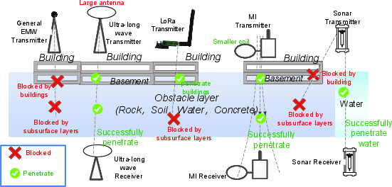
Figure 1: Comparison of the penetration abilities of communication approaches. Green and red texts indicate the advantages and disadvantages, respectively.
Applications and TTE-Specific Features
MIC has been deployed in diverse domains, including agriculture, industrial monitoring, underwater sensor networks, body area networks, and TTE scenarios such as mining and deep drilling. TTE MIC is characterized by:
- Long communication ranges (60–1000 m) with extremely low bandwidth (300–500 Hz) and capacity (<10 kbps).
- Severe eddy current losses in conductive media, necessitating very low frequency (VLF) operation and large antenna structures.
- Deployment constraints due to limited underground space and high costs.
- Fast fading and unpredictable channel conditions, especially in mobile or inhomogeneous environments.
These features impose stringent requirements on antenna design, channel modeling, and upper-layer protocol efficiency.
Channel Modeling and Fine-Grained Decomposition
The survey introduces a rigorous decomposition of the MIC channel power gain into four physically interpretable factors:
- Circuit Gain (CSD): Local energy consumption, optimizable via antenna design and impedance matching.
- Space Gain (SSD): Field attenuation due to spatial expansion, fundamentally limited by the d−6 decay in the near field.
- Eddy Gain (ESD): Losses from eddy currents, especially significant in TTE and underwater environments, requiring frequency optimization and, for multilayer media, FEM-based correction.
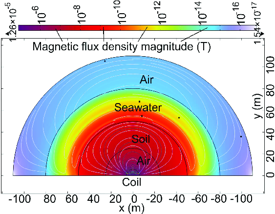
Figure 2: FEM simulation of magnetic flux density in multilayer materials with different conductivities. Here, the conductivities of air, soil and seawater are 0, 0.01, and 4.8 S/m, respectively.
- Polarization Gain (JSD): Losses due to antenna orientation, the primary source of MI fast fading.

Figure 3: Relationship among circuit, eddy, space, and polarization gains. The normal fonts with gray background represent the primary parameters.
This decomposition enables targeted optimization and clarifies the trade-offs in system design, such as the impact of frequency on both circuit and eddy gains.
MI Fast Fading: Modeling, Impact, and Open Problems
The survey is the first to systematically address MI fast fading, which arises from time-varying polarization gain due to antenna vibration and misalignment. Unlike EMWC, where fading is often modeled by Rayleigh or Rician distributions, MI fast fading:
- Cannot be simplified via the central limit theorem due to the low number of independent random variables.
- Exhibits boundary-limited, scenario-dependent distributions (e.g., BCS, boundary p(x)).
- Has unpredictable expectation and variance, often dependent on mechanical factors such as vehicle velocity.
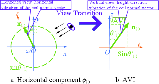
Figure 4: Advised antenna vibration modeling in a 3-D space with independent random variables; n, ϕ, and θ′ denote the normal vector, horizontal and vertical components of the antenna vibration, respectively.
Monte Carlo simulations and geometric models are proposed for practical estimation, but a universal statistical model remains elusive.
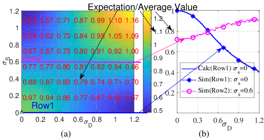
Figure 5: Expectation of MI fast fading JSD for the model in Figure 4.
MI fast fading has profound effects on system performance:
- Average channel power gain can decrease by up to 80% at moderate vibration intensities.
- Outage probability and BER increase sharply with antenna vibration, even at high transmit power.
- Ergodic capacity is significantly reduced, and the coverage region becomes irregular and time-varying.
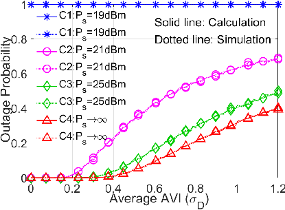
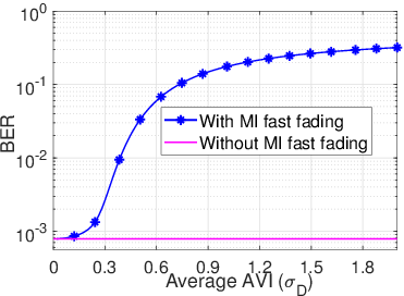
Figure 6: Impact of MI fast fading on MIC performance: (a) Outage probability vs. Rx average AVI; (b) Ergodic capacity vs. Rx average AVI; (c) BER vs. Rx average AVI.
Antenna Design and Point-to-Point TTE MIC
The survey compares four major antenna types:
- Coil: Simple, low-cost, but highly orientation-sensitive.
- Orthogonal MIMO Coils: Mitigate orientation sensitivity, but are difficult to deploy in TTE due to size and crosstalk.
- Rotating Permanent Magnet Antenna (RPMA): Promising for VLF operation and mobile scenarios, but limited by mechanical inertia and maintenance.
- Metamaterial-Enhanced (MSSD0I): High sensitivity and range, but impractically large for most TTE deployments.
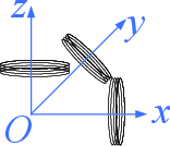
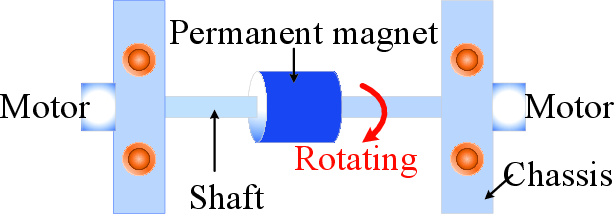
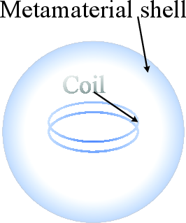
Figure 7: Non-conventional MI antenna types: (a) Orthogonal MIMO coils; (b) RPMA; (c) MSSD1I antenna.
Bandwidth and range analysis reveals that TTE MIC is fundamentally bandwidth-limited, with optimal operating frequencies determined by the trade-off between circuit and eddy gains. Closed-form expressions for range and bandwidth are provided for various scenarios, but numerical methods are often required for inhomogeneous or mixed-field cases.
Relay Techniques, Cooperative MIC, and Crosstalk
Relay-based techniques are essential for extending MIC range and capacity:
- Passive Relays (MI Waveguide, MPRlA): Energy-efficient, but require precise alignment and are sensitive to crosstalk.
- Active Relays (CMIC): More flexible, especially CMIC-1NR for mobile and misaligned scenarios, but with increased protocol complexity and energy consumption.
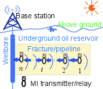
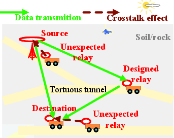
Figure 8: Use cases of relay and CMIC: (a) Pipeline case; (b) Mobile MIC case.
The survey identifies and analyzes both negative and positive crosstalk effects, which can either degrade or enhance performance depending on spatial configuration and frequency. Transformer-based deep learning frameworks are proposed for predicting crosstalk impedance in complex networks.
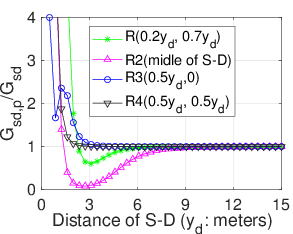
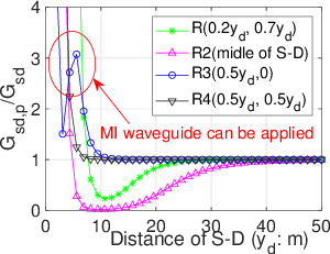
Figure 9: Ratio SSD2 for crosstalk effect as a function of relay position and frequency.

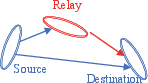
Figure 10: Two types of the CMIC. The topology of CMIC-nAR is similar to the MI waveguide, and signals are transmitted one by one. The coils exhibit a near-perfect alignment. In CMIC-1NR, the coil of the relay does not need to be aligned, and a diversity combining method should be used to combine the relay and source signals.
Network Architecture and Protocol Stack
A comprehensive review of MIC network architecture is provided, mapped to the OSI framework:
- Physical Layer: Channel modeling, resource allocation, and fast fading mitigation.
- Data Link Layer: MAC protocols adapted for directional, low-bandwidth MIC; need for bit-level header compression.
- Network Layer: Frequency- and APO-selective routing, connectivity analysis, and deployment strategies.
- Transport Layer: TCP/IP compatibility is a major challenge due to large headers and RTT suppression; header compression and intelligent retransmission are required.
- Cross-Layer Optimization: Distributed algorithms (e.g., Nash game, RL) are necessary due to limited bandwidth for control information exchange.
The survey highlights the lack of experimental validation for many upper-layer protocols and the need for standardization.
Linux- and TCP/IP-Supported MIC Framework
A novel, implementable MIC framework is proposed, supporting:
- Full TCP/IP stack integration with MI-specific header compression and routing.
- Linux kernel modules for device drivers, MAC, and cross-layer solutions.
- Deep learning platform support (e.g., PyTorch, TensorFlow) for real-time channel estimation and fast fading prediction.
- Hardware/firmware partitioning for time-critical PHY/MAC functions.
This framework enables rapid prototyping, leverages open-source resources, and provides a path toward standardized, scalable MIC deployments.
Open Challenges and Future Directions
Key open problems and research directions include:
- Universal MI fast fading models: Derivation of scenario-independent statistical models, possibly via data-driven or hybrid analytical approaches.
- Deep JSCC and semantic communication: To enable high-dimensional data (e.g., images, video) transmission over ultra-narrowband MIC.
- MCNSI (Communication-Navigation-Sensing Integration): Joint optimization of communication and sensing/localization, balancing conflicting requirements.
- Massive MI MIMO and beamforming: Feasible with RPMA or advanced magnetic sensors, but requires crosstalk mitigation.
- Heterogeneous MIC networks: Spectrum sensing, connectivity, and power optimization in multi-tier, multi-antenna environments.
- TCP/IP adaptation: Dynamic header compression, RTT optimization, and ML-driven protocol adaptation for ultra-low-rate, high-latency links.
- Experimental validation: Robust testbeds and cross-scale channel models for real-world performance assessment.
Conclusion
This survey establishes a rigorous foundation for TTE MIC research, challenging the quasi-static channel assumption and providing a detailed taxonomy of channel, antenna, relay, and network-layer techniques. The proposed Linux- and TCP/IP-supported framework bridges the gap between theoretical advances and practical deployment, enabling integration with SAGUI networks and next-generation mobile systems. The identification of open problems and promising methodologies—especially in MI fast fading, deep learning-based protocol adaptation, and cross-layer optimization—sets the agenda for future research and standardization in this critical field.

